Content last revised on October 14, 2026
DMF50260NFU-FW-21 Identification and Initial Inspection
- Disconnect equipment power and record the DMF50260NFU-FW-21 identification before removing the display cable or disturbing the bezel.
- Compare connector orientation, cable routing, mounting locations, and viewing-window alignment with the existing assembly.
- Inspect the display connector and accessible circuit board for contamination, damaged conductors, and evidence of uneven mechanical loading.
- Identify the controller, contrast-bias circuit, and backlight connections on the equipment schematic before attaching measurement probes.
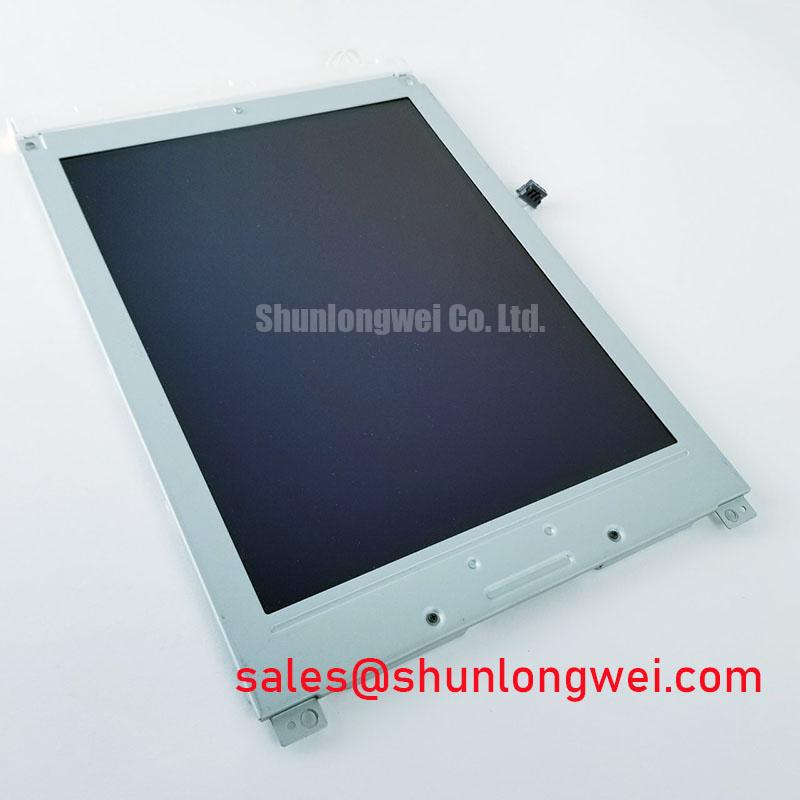
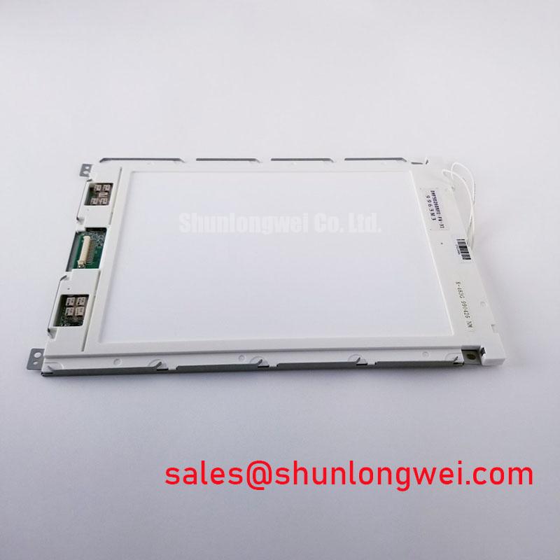
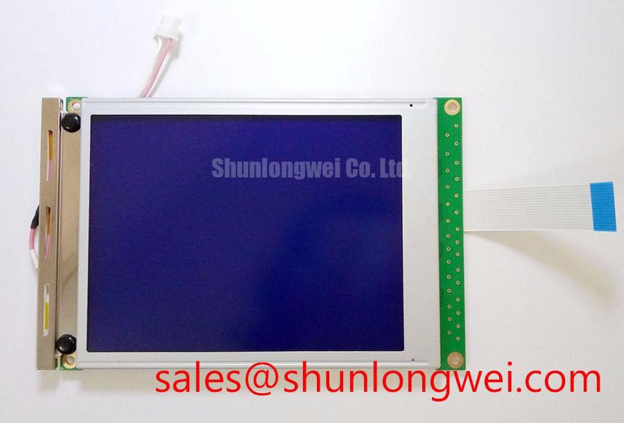
The DMF50260NFU-FW-21 belongs to the Kyocera / OPTREX industrial monochrome LCD family. Replacement evaluation should separate the panel’s identity from the host electronics: a matching outline does not establish compatible drive timing, contrast control, or illumination. The practical objective is to preserve the original electrical and mechanical interfaces while locating the source of the display fault.
| Product attribute | Identification or verification requirement |
|---|---|
| Model | DMF50260NFU-FW-21 |
| Manufacturer | Kyocera / OPTREX |
| Product category | Industrial LCD/HMI panel |
| Display classification | FSTN / STN monochrome passive-matrix LCD |
| Electrical and mechanical acceptance limits | Consult Datasheet for resolution, dimensions, pin assignments, supply and bias voltages, timing, temperature limits, and backlight specification. |
Suppressing Ghosting and Crosstalk via Precision Multi-Level Bias Voltage Dividers
Measure the contrast-bias supply and accessible bias-divider outputs while the display alternates between sparse characters and dense patterns. As a Design Consideration, pattern-dependent ghosting deserves investigation at both the supply and controller: excessive ripple, disturbed divider levels, and incorrect multiplex timing can produce similar visible effects. Compare measurements with the original circuit requirements rather than assigning a fault from appearance alone.
Passive-matrix contrast depends on the effective voltage difference between selected and unselected pixels. An unstable bias network can reduce that distinction, leaving faint unwanted segments or washing out intended characters. Probe grounding matters during this measurement; a long ground lead can introduce interference that resembles supply ripple. Record the waveform at the module connection as well as at the supply source to distinguish distribution problems from regulator behavior.
Where the host schematic includes temperature compensation, inspect the thermistor connection and associated divider components before changing the contrast setting. Evaluate contrast after thermal stabilization within the equipment’s permitted operating conditions. A shifted compensation response and an intermittent bias connection require different corrective actions, even when both appear as temperature-sensitive fading.
The manufacturer’s Kyocera Industrial TFT-LCD Display Technologies resource provides broader display-technology context; TFT characteristics should not be transferred to this passive-matrix product. Active-matrix gamma adjustment is not a substitute for checking the multiplex drive and contrast-bias network involved here.
Data Setup & Hold Time Margin Verification on High-Capacitance Flat Ribbon Flex Cables
Locate the controller’s frame, line, and data-clock signals on the equipment schematic before assessing setup and hold margins. In passive-matrix interface terminology, these functions are commonly described as FLM, LP, and CP; those names are a Design Consideration, not a verified pin assignment for this model. Capture data and its sampling clock at the receiving connector, where cable loading and edge distortion affect the actual timing relationship.
A waveform that looks clean at the controller can arrive with slower transitions or additional ringing after the ribbon cable. Compare the receiver-side transitions against the applicable timing limits, including variations caused by cable position and normal supply changes. Keep probe loading consistent when comparing a suspect assembly with a working one. Intermittent horizontal displacement or corrupted characters warrants checking clock integrity, data order, and controller configuration rather than treating the cable as the sole cause.
💡 Pro Tip: As a Design Consideration, preserve the original cable’s signal-return arrangement and routing before attempting controller timing changes.
Check startup and shutdown behavior as a sequence of events: logic supply, valid scan activity, contrast bias, and illumination control. For passive-matrix operation, sustained unintended DC across the liquid crystal is undesirable; acceptable sequencing must come from the panel and controller requirements. Observe interrupted starts as well as orderly power cycles, because the host’s reset behavior can leave different signal states.
LVDS termination and JEIDA/VESA mapping belong to interfaces that explicitly use those conventions; neither should be assumed for this panel. If the equipment has a separate touch overlay, its communication path also needs independent assessment. The Inter-Integrated Circuit (I2C) bus describes a peripheral interface, not evidence of an integrated touch controller or this LCD’s pixel-data protocol.
Combating Contact Resistance Escalation at Display Connections under Mechanical Vibration
Inspect accessible connector contacts and bezel seating without changing internal compression or opening a bonded display assembly. Missing rows or columns can involve connector continuity, driver behavior, or glass-related faults; their position alone does not establish contact oxidation. Record whether the defect follows cable movement, mounting load, or displayed content before disturbing the assembly.
As a Design Consideration, elastomeric interconnect alignment and compression matter only where the documented construction actually uses that connection method. Likewise, gold-plated internal contact fingers should not be presumed from the product name. For a serviceable connection, follow its assembly procedure and retain the specified spacers and clamping arrangement. Arbitrary tightening can change contact loading and distort the display stack.
Clean only accessible, serviceable contacts with a method approved for the connector and surrounding materials. Prevent solvent from reaching polarizers, adhesives, or the optical cavity. At enclosure level, inspect bracket flatness, cable strain relief, and viewing-window clearance. Uneven mounting pressure can complicate diagnosis by changing the visible defect during handling.
For a precision electronic test and measurement instrument, engineers may evaluate this panel against the existing aperture, viewing direction, and controller interface. The LM64K112 can serve as a comparison reference, not an established interchangeable replacement. Compare actual drawings and electrical requirements before progressing to a substitution trial. The The Ultimate Guide to Industrial TFT LCD Technology offers broader integration background, while passive-matrix-specific checks remain essential here.
CCFL Resonant Inverter Striking Potential & Ignition Arc Fault Prevention
Identify the installed illumination assembly before connecting backlight test equipment; this section applies only where the equipment documentation specifies a CCFL circuit. Striking voltage, sustained lamp voltage, and operating current are properties of the matched lamp-and-inverter arrangement. Generic CCFL values should not become acceptance limits for the DMF50260NFU-FW-21.
As a Design Consideration, investigate intermittent illumination by observing inverter enable, input supply stability, and documented protection outputs. A shutdown can involve lamp loading, connector condition, or inverter malfunction. Use appropriately rated instrumentation and the equipment’s high-voltage service procedure; do not bypass open-load protection to force continued operation.
Inspect accessible high-voltage wiring for damaged insulation, compromised connector seating, and routing that places it near sensitive display signals. Preserve the original separation and insulation provisions. After correcting an identified connection or inverter fault, verify startup and brightness control under the equipment’s permitted conditions, confirming stable illumination without altering the panel’s contrast-bias adjustment.