

Content last revised on September 10, 2026
GPU300HF120D2 Thermal Electrical Optimization: DC Link Capacitance Bank Layout and Low ES Practical Tuning
The GPU300HF120D2 operates within a 1200 V collector emitter rating, but the voltage seen at its power terminals during switching is determined by the complete commutation loop rather than the DC bus measurement alone. In practical service work, inspect the physical path from the DC link capacitor bank to the IGBT terminals and back. Long straps, separated positive and negative conductors, loose laminated busbar hardware, or capacitor leads with unnecessary loop area can increase stray inductance and make turn off overshoot more severe.
As a Design Consideration, the switching peak is influenced by DC bus voltage plus the inductive term created by loop inductance and current transition rate. This is why a voltage probe at the module terminals can reveal a different event from a probe placed remotely on the capacitor bank. Engineers should minimize commutation loop inductance to suppress turn off overshoots, then verify peak voltage margins against the DC link voltage during properly referenced switching tests.
For inverter welders and medium frequency induction heating power supplies, review whether the local DC link capacitors remain mechanically secure and electrically close to the switching bridge. A degraded capacitor connection, uneven busbar contact pressure, or contamination around high current joints can contribute to ringing, heat rise, and irregular current sharing. Snubber component selection is a system level Engineering Recommendation and should be validated from measured switching waveforms, device temperature, and the original converter topology.
The typical 2.30 V VCE(sat) value is an Official Datasheet Specification, not a fixed in circuit voltage reading for every load current, gate condition, or temperature. When comparing service measurements, use the same operating point and probe method as the known good equipment where possible. A rising on state loss indication may require inspection of gate drive amplitude, module mounting contact, cooling performance, bus connections, or load conditions rather than assigning one cause from a single reading.
Assembly Integrity & Layout Architecture: Implementing Long Motor Lead Reflected Wave Voltage for GPU300HF120D2
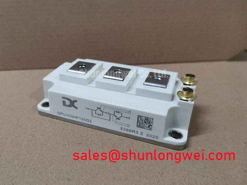
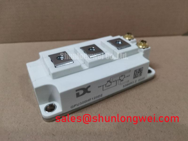
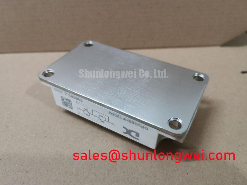
Confirm that the heatsink mating surface is clean, flat, and free of hardened thermal compound before fitting the 62 mm housing. Apply thermal interface material according to the material supplier’s instructions and tighten the mounting hardware using the equipment manufacturer’s documented method. Uneven clamping can impair heat transfer across the module base and make temperature comparison between bridge positions less meaningful.
⚠️ Maintenance Note: During scheduled shutdowns, monitor terminal contact temperature under comparable load and inspect the cooling air path for dust accumulation, blocked filters, moisture residue, and aging thermal interface material.
Long motor cables can behave as transmission lines, so reflected voltage at the motor terminals may become materially different from the voltage observed at the inverter output. This is a Design Consideration for the complete drive system, not a specific guarantee of the IGBT module. Where cable related ringing is suspected, technicians should compare waveform behavior at the inverter output and near the motor using suitable differential measurement equipment. The system designer should assess output reactors, dv dt filters, cable routing, grounding, and motor insulation requirements against the machine documentation.
The gate drive must also be examined as a physical loop. The module has a listed 22.0 nF input capacitance value, which affects the charge and discharge demand presented to the driver. Gate source and sink capability, external gate resistance, gate loop routing, and power emitter reference arrangement all influence switching behavior. A resistor that is acceptable in one inverter may not produce the same result after cable length, DC bus layout, driver board layout, or operating current changes.
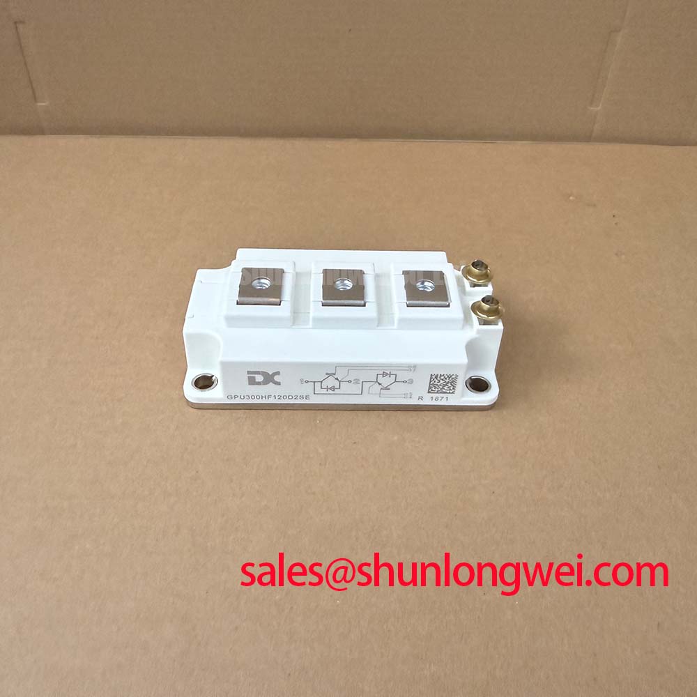
When a repair requires cross model evaluation, compare the complete electrical rating, package geometry, terminal arrangement, gate drive conditions, thermal interface, and protection coordination. The GPU300HF120D2SE should be reviewed only against the original equipment requirements and its own published documentation; a matching current or voltage rating alone does not establish interchangeability.
GPU300HF120D2 Circuit Protection & Reliability: Calibrating Reinforced Insulation Barrier Integrity
Do not infer isolation performance from the IGBT module rating. The GPU300HF120D2 official parameters listed here establish its power semiconductor limits, while reinforced insulation, creepage distance, clearance, and common mode transient performance belong to the driver board, isolator, PCB layout, enclosure, and applicable system safety requirements. The system integrator should verify these properties from the original drive documentation and relevant standards.
Optically coupled or other galvanically isolated drive interfaces are often evaluated where control electronics must remain separated from high energy switching nodes. The operating principle of an optocoupler helps explain why the isolation barrier and its surrounding PCB layout deserve inspection after a power event. Contamination, condensation, carbon tracking, damaged conformal coating, or insufficient spacing around the driver interface can compromise practical isolation behavior even when the power module itself shows no obvious external damage.
Desaturation based protection is commonly used in IGBT drive systems to monitor abnormal collector emitter behavior while the device is commanded on. Soft turn off timing, short circuit response, semiconductor fuse coordination, and DC bus discharge behavior are system dependent Design Considerations. Service personnel should confirm that the original protection path is functional before returning equipment to production, including the driver supply rails, fault latch response, gate command polarity, and controller interlock logic.
Gate emitter voltage must remain within the official ±20 V maximum rating. Negative gate bias, if present in the existing driver, should not be altered casually during repair. Its effect depends on the actual driver architecture, common mode noise environment, resistor network, and switching layout. For structured verification of gate loop behavior, transient immunity, and controlled switching tests, see Precision Gate Drive Design.
GPU300HF120D2 Circuit Protection & Reliability: Calibrating DC Bus Operating Voltage Headroom Derating
The 1200 V VCES rating defines the official maximum collector emitter voltage capability of this module under the manufacturer’s specified conditions. It should not be treated as the normal DC bus target. Designers should evaluate the intended operating bus voltage together with switching overshoot, regeneration events, supply tolerance, fault conditions, temperature, and the protection response of the complete power stage. Peak values should be verified at the module terminals under representative operating conditions.
Altitude, ambient temperature, enclosure cooling, and humidity can affect system level insulation coordination and thermal management. No field failure rate, service life estimate, terrestrial neutron sensitivity, single event burnout rate, or altitude derating figure is asserted here because those values require applicable manufacturer data and qualified system level evidence. For equipment installed outside its original environmental conditions, the responsible system engineer should review insulation coordination, cooling capacity, condensation control, and DC bus operating limits against the governing equipment specification.
In preventive maintenance programs, retain records of heatsink cleaning, fan performance, terminal re torque checks using the equipment procedure, and fault history from the controller. If repeated overcurrent or desaturation events occur, isolate the root condition through controlled measurement of the load, bus voltage, gate commands, cooling condition, and protection timing before replacing power components. This approach protects the replacement module and provides a more reliable basis for restoring industrial inverter welder or induction heating equipment to service.