IGBT Module Selection: Balancing System Voltage, Power Density, and Integration from 600V to 1700V
The Critical First Step: Why IGBT Voltage Rating Dictates Your Entire Power System Design
In modern power electronics, selecting an Insulated Gate Bipolar Transistor (IGBT) module is one of the most consequential decisions an engineer makes. This choice extends far beyond a simple component on a bill of materials; it establishes the foundational architecture of the entire system. The voltage rating (VCES) of an IGBT module directly dictates the maximum allowable DC bus voltage, which in turn influences everything from insulation and creepage distance requirements to the design of magnetic components and capacitor banks. Making the wrong choice can lead to cascading challenges, including compromised safety, reduced reliability, and increased system cost. This guide provides a comprehensive framework for navigating the trade-offs between system voltage, power density, and level of integration when selecting IGBTs from the 600V, 1200V, and 1700V classes.
Decoding Voltage Classes: A Practical Guide to 600V, 1200V, and 1700V IGBTs
The nominal voltage rating of an IGBT module must provide a sufficient safety margin above the system’s maximum DC bus voltage to withstand overshoots caused by stray inductance during switching events. A common rule of thumb is to select an IGBT with a voltage rating 1.5 to 2 times the maximum DC link voltage. This margin is critical for ensuring the device operates within its Safe Operating Area (SOA) and for long-term reliability.
600V Class: The Standard for Low-Voltage Applications
IGBT modules rated for 600V are primarily designed for systems connected to 200-240V AC lines. After rectification, this results in a DC bus voltage of approximately 320-400V. These modules are the bedrock of countless low-to-medium power applications.
- Typical Applications: General-purpose inverters, servo drives, home appliance motor controls (e.g., washing machines, air conditioners), and small uninterruptible power supplies (UPS).
- Design Considerations: At this voltage level, system design is relatively straightforward. The primary focus is often on achieving high efficiency and a compact footprint. Intelligent Power Modules (IPMs), which integrate the IGBTs, freewheeling diodes, gate drivers, and protection circuits into a single package, are extremely popular. A prime example is the 7MBP150RA060, a 600V/150A seven-pack IPM that significantly simplifies design and accelerates time-to-market for servo drives and small inverters.
1200V Class: The Industrial Workhorse
The 1200V class is arguably the most versatile and widely used category, serving as the standard for industrial systems operating on 380V, 400V, or 480V AC lines. These line voltages produce DC bus voltages in the range of 540V to 800V, making 1200V IGBTs the ideal choice.
- Typical Applications: High-power industrial motor drives, renewable energy inverters (solar and wind), EV DC fast chargers, and commercial UPS systems.
- Design Considerations: These applications demand a balance of high performance, robustness, and cost-effectiveness. The FF600R12ME4, a 1200V/600A half-bridge module, is an industry benchmark. Its robust design and standard EconoDUAL™ 3 package make it a go-to solution for building reliable, high-power converters. At this power level, designers have more flexibility in choosing between discrete modules and highly integrated solutions. For more insights on this trade-off, see our guide on the core trio of IGBT module selection.
1700V Class: Powering High-Voltage Systems
When DC bus voltages exceed 900V, engineers must step up to the 1700V class. These modules are essential for systems connected to 690V AC lines, a common standard in heavy industrial machinery, large-scale wind turbines, and medium-voltage drives.
- Typical Applications: Multi-megawatt wind turbine converters, large industrial drives (e.g., in mining or marine propulsion), and medium-voltage grid infrastructure.
- Design Considerations: Designing with 1700V modules requires meticulous attention to insulation, clearance, and managing higher dV/dt rates. The benefits, however, are significant: operating at a higher voltage reduces I²R losses in cabling and can lead to more efficient overall system performance. The 6MBI450VM-170-50, a 1700V/450A module, is engineered for these demanding environments, offering the necessary reliability and performance for high-power conversion.
Key Takeaways: The choice of voltage class is the first and most critical filter in the selection process. It is directly determined by the AC line voltage and the resulting DC bus voltage, with a safety margin of at least 1.5x being essential for robust design.
The Integration Dilemma: Standard IGBT Modules vs. Intelligent Power Modules (IPMs)
After determining the voltage class, the next key decision is the level of integration. The choice between a standard (discrete) IGBT module and a highly integrated Intelligent Power Module (IPM) hinges on balancing design flexibility, time-to-market, and in-house engineering expertise.
Standard IGBT Modules: The Case for Flexibility and Performance
Standard IGBT modules, like the FF600R12ME4 and 6MBI450VM-170-50, contain the IGBT chips and freewheeling diodes in a specific configuration (e.g., half-bridge, six-pack). This approach gives the design engineer complete control over the gate drive circuit, protection schemes, and overall layout.
- Advantages: Maximum design flexibility, ability to optimize gate drive for specific switching characteristics (balancing losses vs. EMI), and often a lower component cost for the power stage itself.
- Challenges: Requires significant R&D effort and expertise in gate driver design, protection circuit implementation, and PCB layout to minimize parasitic inductance. This path leads to a longer development cycle.
Intelligent Power Modules (IPMs): The Path to Simplified Design and Reliability
IPMs are subsystems that bundle the power switches with optimized gate drivers and a suite of protection features like under-voltage lockout (UVLO), short-circuit protection (SCP), and over-temperature feedback.
- Advantages: Drastically reduced design complexity and faster time-to-market. The integrated, pre-validated solution minimizes common design pitfalls related to gate drive and protection, leading to higher system reliability.
- Challenges: Less design flexibility, as the gate drive characteristics are pre-optimized. The initial component cost of an IPM can be higher than a discrete module, although this is often offset by a lower total system cost when R&D, assembly, and component count are considered. The SKiiP39GA12T4V1 is a perfect example of a highly integrated 1200V IPM that delivers high power density by combining advanced silicon with a sophisticated driver and protection unit.
Decision Framework: A Comparative Table
| Parameter | Standard IGBT Module | Intelligent Power Module (IPM) |
|---|---|---|
| Design Complexity | High (Requires expert gate drive and protection design) | Low (“Plug-and-play” approach) |
| Time-to-Market | Longer (Extensive R&D and validation) | Faster (Reduced development cycle) |
| Performance Optimization | High (Full control over switching characteristics) | Moderate (Pre-optimized for balanced performance) |
| System Reliability | Dependent on design expertise | High (Integrated, pre-validated protection) |
| Footprint | Larger (Module + external driver/protection components) | Smaller (Highly integrated) |
Key Takeaways: The choice between a standard module and an IPM is a strategic one. IPMs offer speed and reliability, making them ideal for projects with tight deadlines or for teams looking to focus on system-level innovation. Standard modules provide the ultimate flexibility for engineers needing to extract every last bit of performance for a highly specialized application.
From Silicon to System: How Packaging Impacts Power Density and Thermal Management
The final pillar of the selection process is the module’s packaging. The package does more than just house the silicon; it defines the module’s thermal performance, electrical isolation, and mechanical robustness, directly impacting the achievable power density of the final system. As explored in our article on how IGBT packaging dictates performance, this is a critical consideration.
Standard Packages (e.g., 62mm, EconoDUAL™)
Industry-standard packages like the EconoDUAL™ 3 used for the FF600R12ME4 provide a well-understood and reliable platform. They feature a copper baseplate that spreads heat from the chips to a heatsink. This design has been proven in the field for decades and offers excellent performance for a wide range of applications.
Advanced Integrated Packages (e.g., SKiiP, MiniSKiiP®)
To push power density further, manufacturers have developed advanced packaging technologies. For example, Semikron’s SKiiP technology, often found in high-performance IPMs like the SKiiP39GA12T4V1, can utilize baseplate-less designs with pre-applied thermal interface material and pressure-contact mounting systems. These innovations reduce the overall thermal resistance from the chip to the heatsink, allowing for more efficient cooling and thus higher output current from the same silicon area.
The Thermal Management Imperative
Ultimately, the power an IGBT module can deliver is limited by its ability to dissipate heat. The thermal resistance from junction to case (Rth(j-c)) is a key datasheet parameter. A lower Rth(j-c) means the package is more efficient at transferring heat away from the silicon. Advanced packaging, combined with effective system-level cooling (e.g., high-performance heatsinks, liquid cooling), allows engineers to either push more power through a given module or operate it at a lower, more reliable junction temperature for the same power output.
Key Takeaways: Do not underestimate the role of the package. It is the critical link between the semiconductor and the cooling system. Advanced packages can unlock significant gains in power density, but require careful consideration of the entire thermal and mechanical design.
Practical Application Checklist: Key Questions to Ask Before Finalizing Your IGBT Selection
To bring these concepts together, ask yourself the following questions during your design process:
- What is my maximum DC bus voltage under all conditions? This is the primary driver for selecting the 600V, 1200V, or 1700V class. Always ensure a sufficient safety margin.
- What are my power density and space constraints? A tight space may favor a highly integrated IPM or a module with advanced, thermally efficient packaging.
- What is the target reliability and lifetime for the system? An IPM with integrated, validated protection features can inherently increase system reliability.
- How experienced is my design team with gate drivers and protection circuits? If expertise is limited, an IPM can de-risk the project and significantly shorten the development timeline.
- What is my project’s time-to-market pressure? For fast-track projects, IPMs provide a clear advantage by reducing the design, layout, and testing phases associated with discrete gate drive circuits.
Conclusion: Making the Right Trade-offs for a Future-Proof Design
Selecting the right IGBT module is a multi-faceted decision that requires a holistic view of the system. It is a careful balancing act between three core pillars: System Voltage, which sets the fundamental electrical requirements; Integration Level, which dictates the trade-off between design flexibility and speed-to-market; and Packaging Technology, which ultimately defines the system’s thermal limits and power density. By methodically evaluating your requirements against these three axes—from the foundational 600V/1200V/1700V choice to the strategic decision between a standard module and an IPM—you can build a power conversion system that is not only efficient and compact but also robust and reliable for years to come.
Infographic: A Visual Guide to IGBT Module Selection
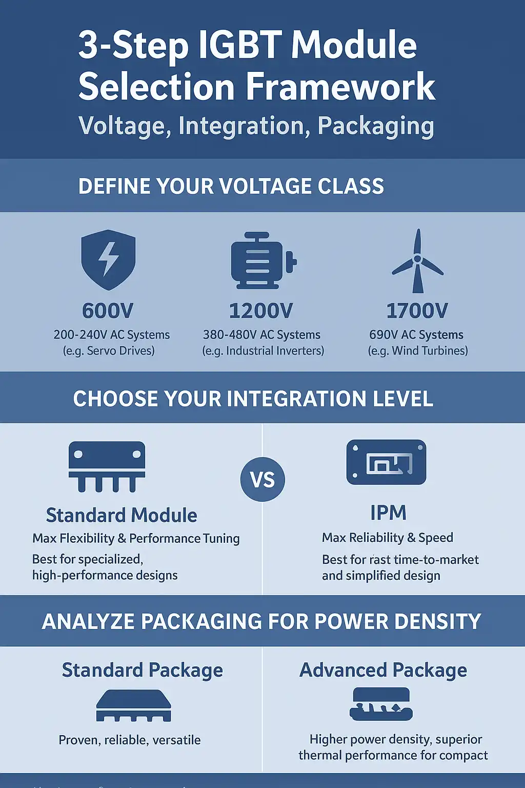
- Title: 3-Step IGBT Selection Framework: Voltage, Integration, Packaging
- Core Concept: A quick decision guide for engineers to choose the right IGBT module by balancing system requirements across three key areas.
- Key Sections & Visuals:
- Point 1: Define Your Voltage Class. [Icon: A shield with a voltage symbol]
- 600V: For 200-240V AC Systems (e.g., Servo Drives)
- 1200V: For 380-480V AC Systems (e.g., Industrial Inverters)
- 1700V: For 690V AC Systems (e.g., Wind Turbines)
- Point 2: Choose Your Integration Level. [Icon: Two puzzle pieces, one separate, one interlocked]
- Standard Module: Max Flexibility & Performance Tuning. Best for specialized, high-performance designs.
- IPM (Intelligent Power Module): Max Reliability & Speed. Best for fast time-to-market and simplified design.
- Point 3: Analyze Packaging for Power Density. [Icon: A chip with arrows indicating heat dissipation]
- Standard Package: Proven, reliable, versatile.
- Advanced Package: Higher power density, superior thermal performance for compact designs.
- Point 1: Define Your Voltage Class. [Icon: A shield with a voltage symbol]
- Branding: Include Logo: Shunlongwei Co., Ltd. | Website: https://www.slw-ele.com
Related Arcticles:
-
- https://www.slw-ele.com/resources/a-strategic-guide-to-igbt-module-selection-balancing-voltage-integration-and-power-density
- https://www.slw-ele.com/ipm-vs-discrete-igbt-a-strategic-guide-to-power-stage-design.html
- https://www.slw-ele.com/mastering-igbt-thermal-management-a-guide-to-packaging-rth-and-heatsink-design.html
- https://www.slw-ele.com/mastering-1200v-igbts-in-industrial-inverters-a-deep-dive-into-vcesat-and-eon-eoff-for-optimal-efficiency.html