

Content last revised on April 14, 2026
Infineon FF600R12ME4: High-Efficiency 1200V IGBT Module for Power Conversion Systems
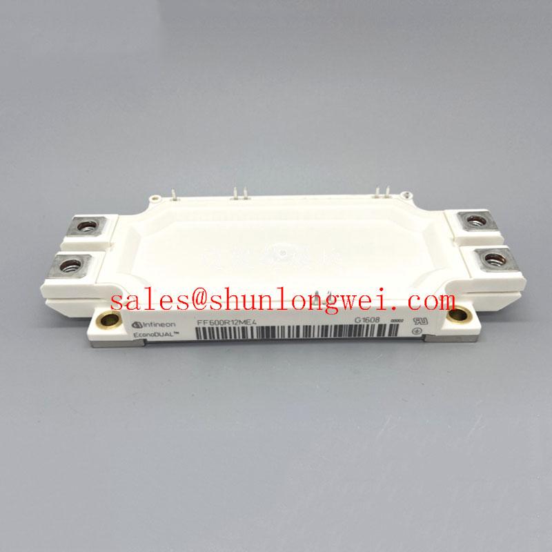
Introduction to the FF600R12ME4 IGBT Module
Optimizing System Efficiency with Advanced IGBT4 Technology
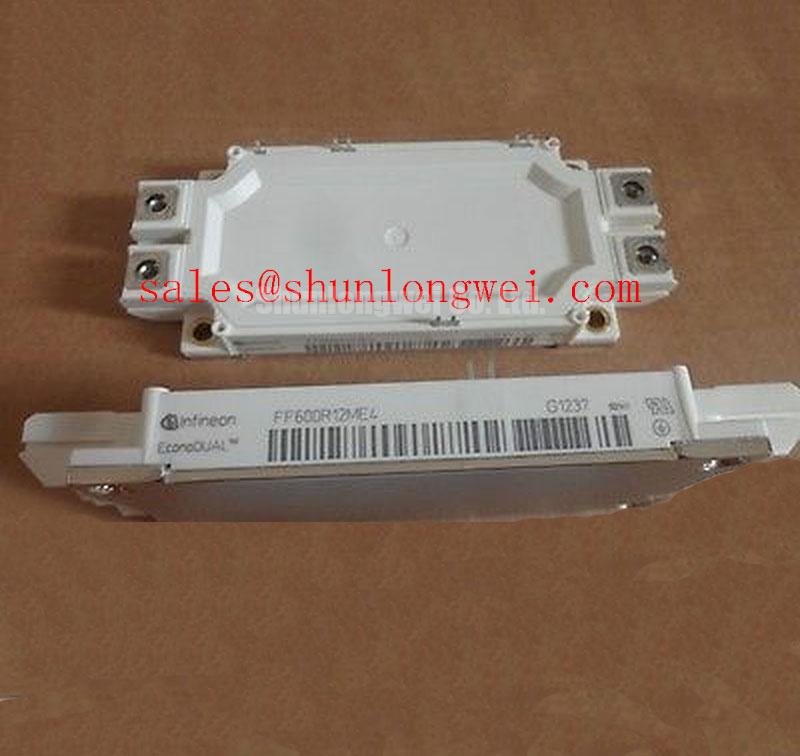
The Infineon FF600R12ME4 is an EconoDUAL™ 3 IGBT module engineered to minimize conduction losses, delivering superior efficiency and thermal stability for high-power conversion systems. Featuring key specifications of 1200V | 600A | VCE(sat) 1.75V (typ.), this module provides exceptional thermal performance and robust operational reliability. It directly addresses the engineering challenge of reducing system heat load and improving power density. For high-current motor drives and inverters prioritizing low on-state voltage, the FF600R12ME4's Trench/Fieldstop IGBT4 design offers a decisive advantage.
Application Scenarios & Value
Achieving System-Level Benefits in High-Current Inverters
The FF600R12ME4 is engineered for applications where electrical efficiency and long-term reliability are paramount. Its robust characteristics make it a foundational component in a variety of high-power systems.
- Motor Drives: In industrial motor control, particularly for large conveyor belts or pumps, managing heat is a primary engineering challenge. The FF600R12ME4's low collector-emitter saturation voltage (VCE(sat)) of 1.75V (typical at 25°C) directly translates to lower power dissipation during operation. This reduction in waste heat allows for more compact heatsink designs or higher power output from an existing thermal management system.
- High-Power Converters: For central solar inverters and wind turbine converters, maximizing energy harvest is the core objective. The module's Trench/Fieldstop IGBT4 technology provides a balanced performance between conduction and switching losses, ensuring high conversion efficiency across a wide range of operating conditions.
- Uninterruptible Power Supplies (UPS): In large-scale UPS systems, reliability is non-negotiable. The integrated NTC thermistor provides real-time temperature feedback, enabling precise thermal monitoring and protection, which is critical for ensuring system availability during power disturbances.
For systems that require operation at a higher voltage class, the related FF600R17ME4 offers a 1700V capability within a similar package family.
Key Parameter Overview
Decoding the Specs for Enhanced Switching Performance
The technical specifications of the FF600R12ME4 are foundational to its performance in demanding applications. The parameters below are selected to provide engineers with the critical data needed for system design and evaluation, focusing on the trade-offs between conduction and switching performance.
| Parameter | Symbol | Value | Engineering Value & Interpretation |
|---|---|---|---|
| Collector-Emitter Voltage | VCES | 1200 V | Provides the necessary voltage headroom for operation in standard 400V to 690V AC line applications, ensuring a robust safety margin against transient overvoltages. |
| Continuous DC Collector Current | IC nom | 600 A (at TC = 100°C) | Defines the module's high current handling capability under realistic industrial case temperatures, enabling its use in high-power motor drives and inverters. |
| Collector-Emitter Saturation Voltage | VCE(sat) | 1.75 V (typ. @ 25°C, IC=600A) | This is a direct measure of on-state efficiency. A low VCE(sat) is like a water pipe with very little friction; it allows current to flow with minimal energy loss as heat, simplifying thermal design. |
| Total Switching Energy | Ets | 130 mJ (typ. @ 150°C) | Represents the energy lost during each turn-on and turn-off cycle. The IGBT4 technology offers a controlled balance, making it suitable for applications with moderate switching frequencies where low conduction loss is the priority. |
| Thermal Resistance, Junction to Case | Rth(j-c) | ≤ 0.040 °C/W per IGBT | Indicates how efficiently heat can be transferred from the active silicon die to the module's baseplate. A lower value signifies superior heat extraction, critical for achieving high reliability and power density. |
Download the FF600R12ME4 datasheet for detailed specifications and performance curves.
Technical Deep Dive
Inside the Trench/Fieldstop IGBT4 Technology
The core of the FF600R12ME4's performance lies in its use of Infineon's Trench/Fieldstop IGBT4 technology. This silicon design represents a significant optimization aimed at reducing on-state losses. Think of the VCE(sat) as the "toll" the current must pay to pass through the switch. In older IGBT generations, this toll was higher. The Trench/Fieldstop structure creates a much wider, smoother "highway" for electrons by altering the silicon's internal electric field. This results in a significantly lower voltage drop (VCE(sat)) when the device is fully on, which is the dominant source of power loss in many high-current, moderate-frequency applications like large motor drives. While not optimized for the extreme high frequencies of IGBT7, the IGBT4 provides a robust and highly efficient solution for the mainstream inverter market, prioritizing low conduction losses to improve overall system efficiency and thermal stability.
Frequently Asked Questions (FAQ)
What is the primary benefit of the Trench/Fieldstop IGBT4 technology in the FF600R12ME4?
The primary benefit is a significantly lower VCE(sat) compared to older non-punch-through or field-stop technologies. This directly reduces conduction power losses (P = VCE(sat) * IC), leading to higher inverter efficiency and reduced heatsink requirements.
How does the positive temperature coefficient of VCE(sat) aid in paralleling modules?
As an IGBT chip heats up, its VCE(sat) slightly increases. When multiple FF600R12ME4 modules are paralleled, if one module starts to carry more current and gets hotter, its rising VCE(sat) naturally encourages the current to redistribute to the cooler, parallel modules. This self-balancing effect prevents thermal runaway and ensures stable current sharing without complex external circuitry.
What is the function of the integrated NTC thermistor?
The built-in Negative Temperature Coefficient (NTC) thermistor acts as a temperature sensor. Its resistance decreases predictably as the module's temperature rises. This allows the system's control unit to accurately monitor the IGBT's operating temperature, enabling crucial functions like over-temperature protection and dynamic performance optimization.
Is the EconoDUAL™ 3 package suitable for high-vibration environments?
The EconoDUAL™ 3 package is designed for industrial applications and is qualified according to relevant IEC standards for mechanical robustness. The screw terminals provide secure electrical and mechanical connections, making it well-suited for systems like motor drives and wind turbines that may experience operational vibrations.
For a new design, what is a key consideration when implementing the FF600R12ME4?
A key consideration is the gate drive design. To leverage the module's switching characteristics and ensure reliable operation, the gate driver circuit must be able to supply the specified peak gate currents and maintain stable +15V/-15V gate voltages, as detailed in the datasheet, to fully turn the device on and off cleanly.
An Engineer's Perspective on Deployment
From a design engineer's viewpoint, the FF600R12ME4 is a workhorse module that prioritizes efficiency and thermal headroom. Its low VCE(sat) is not just a datasheet number; it's a critical enabler for pushing power density limits or for meeting stringent efficiency targets like those in modern grid-tied inverters. The proven reliability of the EconoDUAL™ 3 housing, combined with the predictable performance of the IGBT4 silicon, reduces design risk. It allows the engineering team to focus on system-level optimization, confident in the thermal stability and electrical performance of the core power stage.