


Content last revised on January 31, 2026
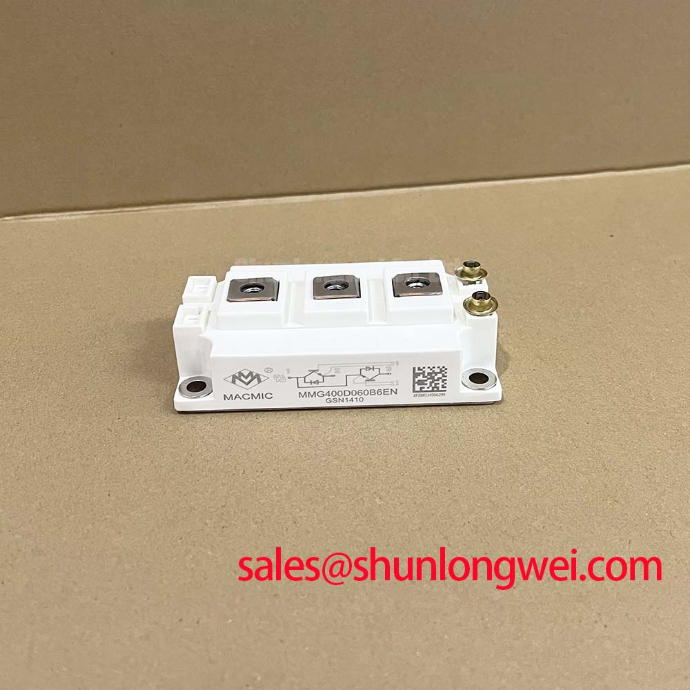
MMG400D060B6EN | 600V 400A Dual IGBT Module for High-Efficiency Inverters
An Engineering-Focused Overview of the MMG400D060B6EN IGBT Module
This 600V/400A Dual IGBT module is engineered to minimize total power losses in high-frequency switching applications, directly addressing the core demands of modern power conversion systems. It integrates low on-state voltage and fast switching characteristics to deliver tangible performance gains. Key specifications include a 600V collector-emitter voltage, a 400A continuous collector current, and a typical VCE(on) of 1.7V. The primary engineering benefits are a significantly reduced thermal load on system cooling components and the capability to design for higher power density. For motor drives and solar inverters operating up to 20kHz, the MMG400D060B6EN offers a compelling balance of conduction and switching efficiency.
Application Scenarios & Value
System-Level Benefits in High-Frequency Power Conversion
The MMG400D060B6EN is engineered for applications where efficiency and power density are critical design drivers. Its performance characteristics make it a strong candidate for the power stages of Variable Frequency Drives (VFDs), industrial servo drives, high-frequency welding equipment, and uninterruptible power supplies (UPS).
Consider the design of a compact Variable Frequency Drive (VFD) for a 100 kW industrial motor. A primary engineering challenge is managing the heat generated within a space-constrained enclosure while meeting stringent energy efficiency standards. The MMG400D060B6EN addresses this directly. Its low typical VCE(on) of 1.7V at its nominal current rating minimizes conduction losses during the on-state. Concurrently, its low turn-off switching energy (Eoff) of 25 mJ (typ.) curtails losses that become dominant as the switching frequency increases. This dual-front reduction in power loss allows engineers to specify smaller, more cost-effective heatsinks and potentially use a smaller enclosure, contributing to a lower total cost of ownership. For systems operating on a higher voltage bus, the related BSM300GA120DN2 offers a 1200V rating.
Key Parameter Overview
Data-Driven Insights for System Design
The technical specifications of the MMG400D060B6EN provide a clear picture of its capabilities. The parameters below are grouped by function to facilitate efficient evaluation for your specific application's requirements.
| Absolute Maximum Ratings (Tj = 25°C unless otherwise specified) | ||
|---|---|---|
| Parameter | Symbol | Value |
| Collector-Emitter Voltage | VCES | 600V |
| Continuous Collector Current (Tc = 80°C) | IC | 400A |
| Pulsed Collector Current | ICM | 800A |
| Gate-Emitter Voltage | VGES | ±20V |
| Power Dissipation (Tc = 25°C) | PD | 1785W |
| Static Electrical Characteristics | ||
| Collector-Emitter On-State Voltage (IC = 400A, VGE = 15V, Tj=25°C) | VCE(on) | 1.7V (Typ), 2.1V (Max) |
| Gate-Emitter Leakage Current (VGE = ±20V) | IGES | ±500nA |
| Collector-Emitter Cutoff Current (VCE = 600V) | ICES | 1mA |
| Dynamic Electrical Characteristics | ||
| Turn-On Energy (IC = 400A, VCC = 300V) | Eon | 38 mJ (Typ) |
| Turn-Off Energy (IC = 400A, VCC = 300V) | Eoff | 25 mJ (Typ) |
| Short-Circuit Withstand Time (Vcc=400V, Vge=15V, Tj=125°C) | tsc | 10 µs |
| Thermal Characteristics | ||
| Thermal Resistance, Junction-to-Case (per IGBT) | Rth(j-c) | 0.07 K/W |
| Operating Junction Temperature Range | Tj | -40 to 150°C |
Frequently Asked Questions
Engineering-Centric Inquiries
What is the primary benefit of the Kelvin emitter pin on the MMG400D060B6EN?
The dedicated Kelvin emitter pin provides a direct, low-inductance return path for the gate drive circuit, separate from the high-current load path of the main emitter. This decoupling prevents load current fluctuations from inducing voltage drops that would otherwise distort the gate-emitter voltage (VGE). The result is cleaner, more precise gate control, leading to faster switching, reduced oscillation, and the ability to fully realize the module's low switching loss potential.
How does the low typical Eoff of 25 mJ influence the design of a power converter?
A lower turn-off energy (Eoff) directly translates to less heat generated during each switching cycle. This benefit becomes exponentially more significant as the system's operating frequency increases. For designers, this allows for two strategic advantages: either pushing to a higher switching frequency to reduce the size of magnetic components like inductors and transformers, or maintaining a conventional frequency and benefiting from lower operating temperatures, which improves system reliability and lifetime.
Technical Deep Dive
Optimizing Switching Performance with the Kelvin Emitter
A closer analysis of the MMG400D060B6EN's design reveals a focus on enabling clean, high-speed switching. The inclusion of an auxiliary Kelvin emitter terminal is central to this design philosophy. In a standard IGBT module, the gate driver shares the emitter connection with the main power circuit. As the module switches hundreds of amperes, parasitic inductance in this shared path (Lσ) causes a voltage drop (V = L * di/dt) that effectively subtracts from the applied gate voltage, slowing down the switching transient.
The Kelvin emitter provides an independent, quiet signal ground for the Gate Drive. Think of it as having a private access road for control signals, completely separate from the congested main highway carrying the power traffic. This ensures the gate driver's output is precisely what the IGBT's gate experiences. This precise control is what allows the module to achieve its specified fast turn-off time and low Eoff, minimizing switching losses and improving reliability by reducing voltage overshoot and ringing.
Actionable Insights for Design Engineers
To evaluate the MMG400D060B6EN for your next power conversion project, request a quote to assess its suitability for your system's performance and cost targets. Our team can provide the necessary information for your procurement process.