Content last revised on October 16, 2026
Eye-Diagram Voltage Margin and Differential Noise Floor Verification in High-Vibration Bays
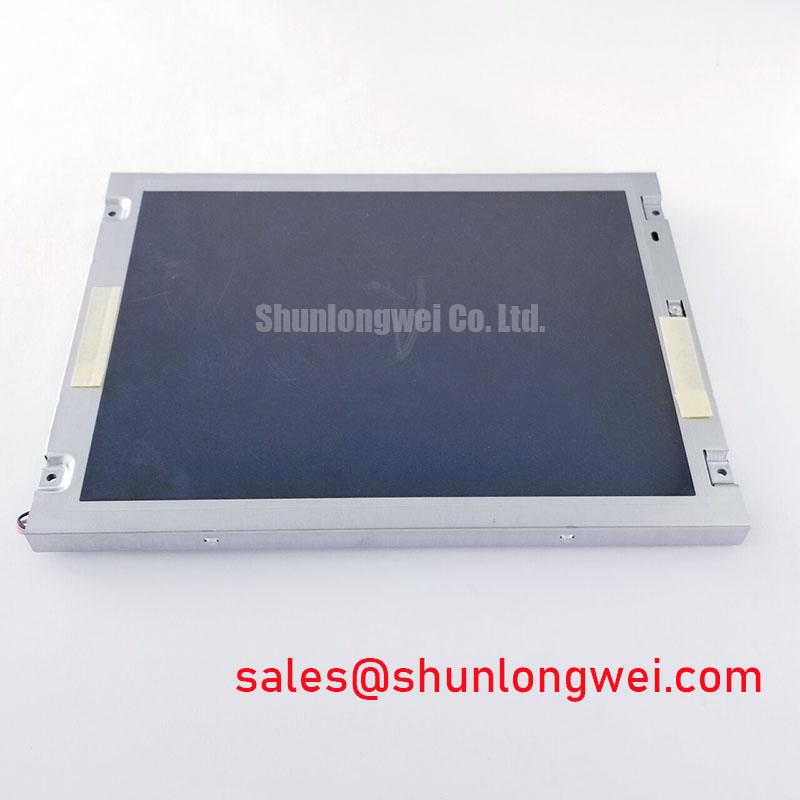
When a substation protection or SCADA console develops pixel jitter, horizontal noise bands, or intermittent image loss, I first isolate the display link from the variable-frequency drive environment. The TM121JDSG10-00 is identified as a Tianma TFT-LCD active matrix color display module, so the replacement assessment must cover the complete panel interface, cable routing, grounding arrangement, and associated controller rather than the glass module alone.
A shielded FFC or LVDS cable should maintain a continuous return path through the enclosure and connector system. The shield termination method is a Design Consideration determined by the cabinet grounding architecture; it should not be treated as a fixed product specification. If common-mode noise is suspected, compare the differential pair at the panel connector with the same signal at the transmitter. A ferrite component can be evaluated as part of the system filter network, but its impedance profile, placement, and current rating must be selected from measured interference rather than assumed to be included with the display.
In high-vibration bays, inspect connector retention, cable bend stress, and chassis movement while monitoring the image. A fault that changes when the cable is gently supported may indicate contact variation, mechanical strain, or a marginal signal path. For cold installations, assess the complete optical and electronic assembly during temperature transition. Liquid-crystal response time and signal timing can change with temperature, so any heater control must be evaluated by the system designer with the actual panel documentation and measured image response.
The Tianma Microelectronics industrial TFT display information resource provides useful manufacturer context for industrial display evaluation. It should be considered alongside the panel-specific documentation when checking interface, environmental, and optical compatibility.
Suppressing Localized Thermal Gradients to Prevent Chronic Optical Yellowing
Thermal mapping around the narrow display edges is more useful than judging color shift from the center of the screen alone. Uneven heat from the backlight driver, nearby power components, or a poorly ventilated enclosure can create local luminance and chromaticity changes. An aluminum heat-spreader rail may be evaluated as a Design Consideration where it improves temperature uniformity, but its dimensions, contact pressure, insulation, and thermal interface must be determined from the mechanical stack-up.
Do not attribute a 50,000-hour brightness figure to the TM121JDSG10-00 unless that value is explicitly assigned to the exact display and backlight configuration by the relevant technical documentation. LED half-life depends on drive current, junction temperature, optical construction, and operating profile. A backlight driver evaluation should therefore record brightness trend, enclosure temperature, and current regulation under the intended duty cycle. This separates a backlight ageing characteristic from an LCD panel replacement decision.
Optical surface treatment also requires direct confirmation. An anti-glare or anti-reflective finish, if required for strong control-room lighting, should be verified against the original panel specification rather than inferred from the TFT-LCD category. Check reflected control-room lighting at the normal viewing angle, then inspect the image through the enclosure window. Mechanical compression, frame distortion, and uneven mounting can produce visual non-uniformity even when the electrical image signal is stable.
For a same-size or same-resolution replacement review, engineers can place TX31D11VC1CAA into the comparison matrix. The comparison should include connector position, active area, optical stack, interface protocol, backlight arrangement, and enclosure clearance. A similar product category alone does not establish plug compatibility.
VESA versus JEIDA Data Mapping Alignment and Even or Odd Channel Signal Integrity
Split-screen artifacts, inverted color groups, or unstable vertical bands require a protocol check before changing the panel. Confirm the controller output mapping against the receiving panel documentation, including VESA or JEIDA convention, color-bit order, channel assignment, clock polarity, and enable behavior. These are interface-level compatibility conditions, not generic properties that can be safely inferred from the model name.
The logic supply requirement must be taken from the original panel documentation and measured at the panel connector during power-up. Monitor the rise profile, enable sequence, reset behavior, and backlight activation separately. A supply that appears correct with a multimeter can still exhibit overshoot, excessive ripple, or sequencing conflict when the controller and backlight driver start together.
For high-EMI factory environments, route differential pairs as a controlled-impedance transmission path with consistent reference geometry. A nominal 100 Ω differential target is a common industry Design Consideration for LVDS routing, but the final value is governed by the transceiver, cable, connector, stack-up, and receiver specification. Keep pair geometry continuous through the connector transition and avoid unnecessary stubs. Check intra-pair skew and clock quality at the receiver with suitable probing; the acceptable timing margin belongs to the complete link.
⚠️ Field Alert: Disconnect cabinet power and allow stored energy to discharge before removing the panel cable, because live insertion can expose signal pins and power contacts to avoidable electrical stress.
When the panel is part of a larger display chain, the associated backlight or display solution can be reviewed beside TX17D02VM2CAA-2. Treat that device as a separate component in the topology review and verify its electrical interface, control method, and protection behavior independently.
Suppressing Acoustic Capacitor Buzz and EMI Emissions across PWM Frequencies
Audible buzz near a display assembly should be traced to the actual power path rather than assigned automatically to the LCD module. Inspect the backlight driver, inductors, transformers, capacitors, mounting surfaces, and PWM control wiring while changing the operating condition in a controlled manner. A legacy CCFL inverter and a constant-current LED driver have different ignition, regulation, and electromagnetic behavior; the correct topology must be identified from the installed equipment documentation.
The TM121JDSG10-00 listing identifies the product as a TFT-LCD active matrix color display module, but it does not establish a specific CCFL ignition voltage, LED PWM ratio, backlight lifetime, MTBF value, or acoustic emission limit. Those figures belong to the confirmed panel and driver assembly. During repair, record whether the symptom is image loss, dimming, visible flicker, audible vibration, or a protection shutdown, then correlate it with the driver status output and backlight current waveform.
Backlight open-circuit and short-circuit protection should be evaluated at the driver level. Check whether the protection output is latched, periodically retried, or reported through the host controller. This distinction helps separate a failed lamp or LED string from a control, connector, or supply fault. Do not bypass the protection circuit during normal operation; instead, use the manufacturer-approved diagnostic method and verify that the replacement panel matches the driver’s electrical and mechanical interface.
To reduce radiated and conducted interference, keep high-current backlight loops physically separated from the display data path, minimize unnecessary loop area, and bond the enclosure according to the cabinet grounding plan. The result must be assessed through system-level EMC testing; a discrete display module does not independently carry a CISPR or EN 55011 certification for the finished equipment. Reliability and environmental integration guidance is also available in Industrial Display & HMI Solutions, which can support enclosure, vibration, thermal, and interface planning for industrial HMI systems.