
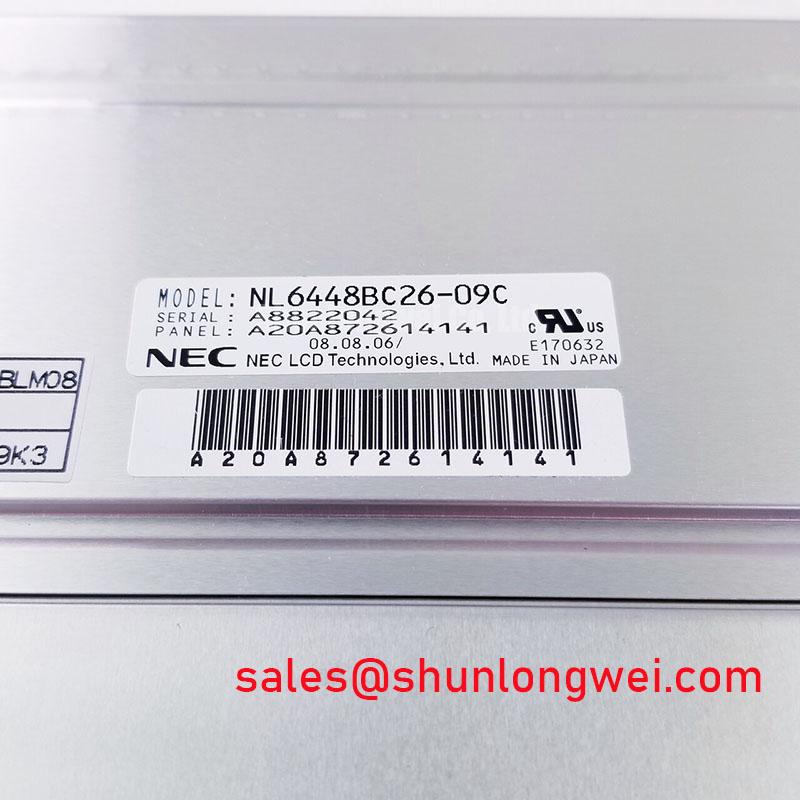
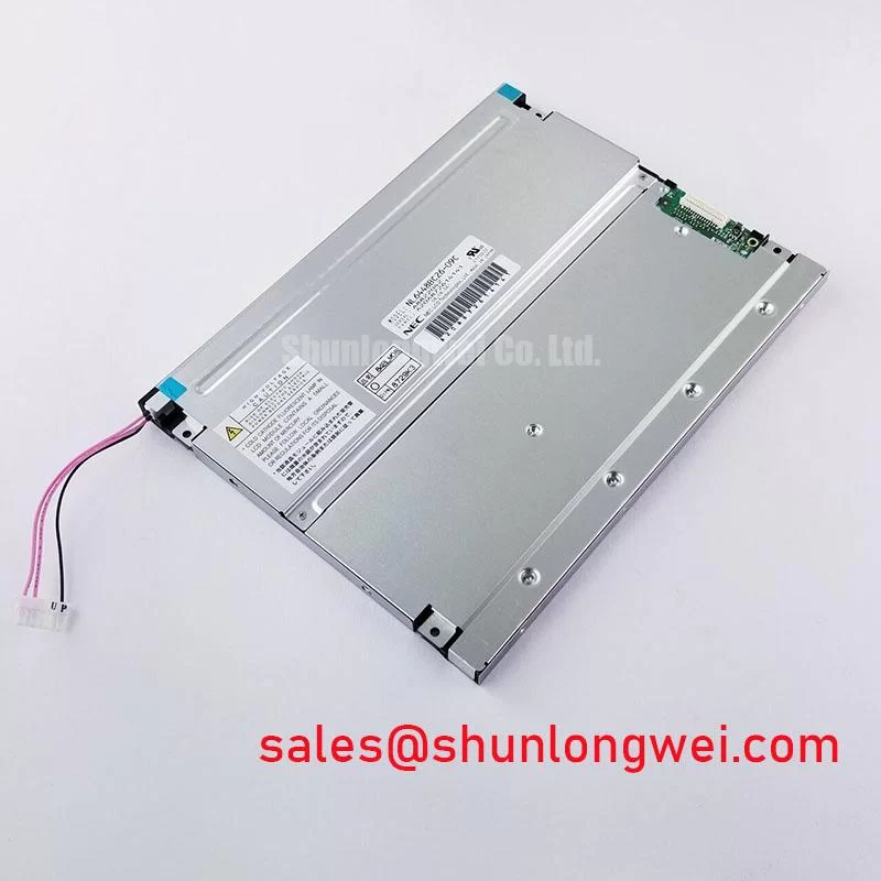


Content last revised on September 10, 2026
Logic Supply Voltage Sequencing for Driver IC Protection
Start the electrical inspection with the host display cable disconnected and the equipment isolated from power. Check the connector for contamination, bent contacts, displaced locking hardware, or uneven insertion depth. A dark display can result from the panel supply, timing controller, video interface, backlight circuit, or cable path, so a voltage reading at one point should not be treated as proof that the panel itself has failed.
The supplied engineering brief identifies 3.3 V and 5.0 V as voltage domains that may require verification during system integration, but those values must not be treated as interchangeable specifications for this exact panel. Measure the power rail at the panel connector during startup and compare its rise profile with the original equipment documentation. Designers should also check whether enable, reset, backlight, and video signals are sequenced according to the host system requirements. Excessive delay, abrupt ramping, or an incorrect enable order can leave the display inactive even when the measured supply appears stable after startup.
For a differential video connection, inspect the complete signal path rather than relying only on continuity testing. The engineering target described for this application uses controlled differential routing and a nominal 100 ohm characteristic impedance as a design consideration. This is not an official factory parameter for the NL6448BC26-09C in the supplied data. Cable construction, connector transitions, PCB stack-up, and termination must be evaluated together by the system designer.
When the screen shows a split image, unstable synchronization, or repeated vertical bands, compare the suspected unit with a known-good signal path using an oscilloscope or suitable differential probe. Verify the transmitter mode, data mapping, clock polarity, and color order against the original display documentation. JEIDA and VESA mapping are system-level interface choices; they should not be guessed from the model number. Incorrect mapping can create color errors or image segmentation without indicating physical damage to the glass.
Cold-start testing deserves separate attention. Liquid-crystal response can change as ambient temperature falls, and a slower gray-to-gray transition may appear as image trailing or delayed movement. This is a design consideration for equipment exposed to sub-zero conditions, not a confirmed environmental performance claim for this model. If the panel is used in a cold enclosure, engineers should verify the panel’s specified operating range, enclosure heat distribution, startup timing, and any approved heater control method. A heater must be controlled by the complete equipment design, with attention to local temperature gradients and condensation risk.
For a field replacement, record the original startup waveform before removing the failed unit whenever the equipment can still be powered safely. That reference is often more useful than a generic timing assumption because it captures the actual host controller, cable, and power supply behavior. The NL10276BC16-06 panel can be reviewed as a separate same-class replacement candidate, but mechanical fit, connector definition, optical performance, and electrical timing require an independent compatibility check.
Surface Readability Under Strong Ambient Illumination
In a dispatch console or protection terminal, first determine whether the reported fault is an image-generation problem or a viewing problem. Shine a controlled flashlight across the front surface at an angle and observe whether image content remains present beneath the reflection. If characters can be seen only from a narrow position, inspect the viewing environment, cover glass, surface condition, and installation angle before condemning the display module.
The supplied factory data identifies the NL6448BC26-09C as a TFT LCD display module, but it does not provide a verified anti-glare coating type, anti-reflective treatment, viewing-angle specification, touch technology, brightness rating, or contrast value. These characteristics should be confirmed from the applicable original datasheet or equipment service documentation. It is not technically safe to assume that a panel described as industrial grade automatically includes a particular AG or AR surface treatment.
Surface glare is affected by more than the panel itself. Protective windows, adhesive layers, sunlight, overhead lamps, operator position, and dark cabinet interiors can all change perceived readability. A design consideration for high-ambient installations is to evaluate the complete optical stack in the final enclosure rather than testing the bare module on a bench. Any cleaning process should follow the equipment manufacturer’s instructions and avoid pressure on the active area or edge seals.
TN, IPS, and MVA descriptions should also be treated carefully. The supplied information does not confirm the panel technology or a symmetric viewing cone for this exact model. If a replacement is being considered for a multi-operator SCADA console, verify readability from the actual left, right, upper, and lower working positions. A display that appears acceptable directly in front of the bench may produce contrast inversion or tonal changes when installed at the console angle.
Signal integrity remains relevant to optical evaluation. Clock jitter, data hold behavior, and marginal differential levels can create flicker or intermittent image defects that resemble a poor optical response. Confirm the video transmitter settings and compare the clock and data behavior with the known-good equipment path. The specified test conditions should include the intended temperature range because cable characteristics, connector contact quality, and controller timing can shift with enclosure temperature.
Backlight troubleshooting must remain separate from image-path troubleshooting. If a flashlight reveals a faint image while the screen appears dark, inspect the backlight supply, enable signal, current regulation, and protection feedback in the host equipment. The supplied factory context does not confirm whether this particular unit uses a specific backlight type, rated lifetime, constant-current topology, or open and short circuit protection behavior. Those functions belong to the documented panel and system design and must be verified rather than inferred.
For related display-chain evaluation, engineers may review NL10276BC30-24D as a separate NEC display solution. It should be considered a distinct product, not an automatic accessory or electrically interchangeable companion for the NL6448BC26-09C.
Eye Diagram and Differential Noise Verification in High-Vibration Bays
When a display is installed near switching equipment, begin with physical routing. Separate the display cable from high-current power conductors where the enclosure permits, avoid sharp bends at the panel connector, and confirm that the cable shield and chassis bonding follow the original equipment design. A shield that is folded into the connector latch or left floating can behave differently from the intended installation.
Noise near variable-frequency drives may appear as horizontal bands, pixel jitter, intermittent loss of synchronization, or random color disturbance. None of these symptoms identifies one certain cause. Compare the panel with a known-good unit, observe the differential clock and data signals at the receiver path, and inspect the fault under the same motor operating conditions. If the symptom changes when the cable is moved, the result may indicate a routing, contact, grounding, or impedance issue that requires further measurement.
The engineering brief references 100 ohm differential routing and a skew objective of no more than 50 ps. These are system-level design considerations supplied for the intended analysis, not confirmed factory ratings of the NEC panel. The actual margin depends on the transmitter, receiver, cable, connector, trace length, dielectric structure, and termination. Engineers should verify the eye opening at the receiving interface under the worst practical switching and temperature conditions.
Common-mode ferrites can sometimes reduce conducted interference, but their effect depends on the cable, frequency spectrum, signal amplitude, and grounding arrangement. Adding a ferrite without checking the differential waveform may introduce unwanted loss or edge distortion. Selective testing with and without the suppression component is more reliable than assuming that every noise band requires the same filter.
Vibration adds a mechanical variable to an electrical problem. Check whether the panel frame, cable clamp, and connector support allow the cable to move against the connector during operation. Inspect the connector after vibration testing for fretting, partial disengagement, or uneven pressure. The mounting method must support the module without transferring concentrated force into the glass or flex region. Exact mounting hardware and torque should come from the equipment mechanical drawing.
⚠️ Field Alert: Disconnect power and allow the host equipment to discharge before inserting or removing the display cable, because live connector handling can expose signal and supply contacts to unintended electrical stress.
For enclosure-level guidance covering industrial HMI integration, thermal management, vibration, and interface planning, consult the Industrial Display & HMI Solutions engineering resource. It provides broader application context while the exact limits for this model remain subject to the applicable factory documentation.
Glass and Driver Connection Stress During Mechanical Service
Handle the NL6448BC26-09C by its frame or approved mounting surfaces, not by pressing the active glass area. During removal, release the cable lock before applying extraction force and support the module so that the flex cable is not used as a lifting point. A display may continue to show an image while suffering an intermittent edge connection, so visual operation during a short bench test does not eliminate the need for a careful mechanical inspection.
Micro-twist, uneven frame pressure, and localized impact can create difficult intermittent faults. A practical diagnostic sequence is to display solid red, green, and blue screens, followed by white and black fields, while observing the panel at normal viewing distance and under angled illumination. Look for fixed lines, localized shadowing, color contamination, or changes triggered by gentle movement of the cable support rather than the glass. This test helps separate a video-path problem from a backlight or panel-area defect, but it does not establish a single failure mechanism by itself.
A 45-degree flashlight inspection can help reveal faint image content, edge shadowing, surface damage, or uneven illumination. Perform it with the panel mounted in a stable position and compare results with a known-good reference. Do not press the glass or twist the frame while testing. If the image changes when the chassis is flexed, stop the test and inspect the mounting plane, fastener loading, frame distortion, and cable strain relief.
The supplied information does not confirm a particular COG construction, driver bump design, touch layer, or internal bonding material for this model. Such internal details should not be inferred from a symptom. If a repair requires touch functionality, glove operation, wet-finger response, or a resistive versus capacitive interface, verify those features in the original system documentation before ordering or installing a replacement.
PWM behavior also requires documentation-based verification. The engineering brief references a possible 200 Hz to 1 kHz dimming range for system evaluation, but this is not an official factory parameter supplied for the NL6448BC26-09C. If the host uses PWM brightness control, measure the actual enable or dimming waveform, confirm the panel’s accepted control method, and evaluate visible flicker, acoustic behavior, and brightness linearity on the complete assembly. The system designer must determine the suitable frequency and duty-cycle operating conditions from the documented backlight interface.
Before closing the equipment, compare the replacement panel’s connector orientation, active-area position, mounting points, cable reach, and rear clearance with the removed unit. Confirm the image through a complete power cycle, not only through a warm restart. Record the supply behavior, image stability, backlight response, and cable retention so future maintenance staff have a useful baseline for the same SCADA or industrial HMI assembly.