

Content last revised on October 8, 2026
104PW161 Circuit Protection and Reliability: Checking Wiring and Switching Transients
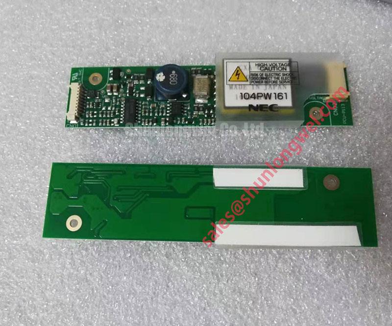
Begin service inspection by isolating the equipment, checking the 104PW161 identification against the replacement record, and confirming that the original wiring and mounting arrangement match the application documentation. The 104PW161 is an NEC LCD backlight inverter module, not a TDK-Lambda industrial power supply or a forklift traction component. Verify the input requirements, connector pinout, control signals, and supported backlight configuration against the original module and display documentation before energizing the assembly.
| Parameter | Product Information |
|---|---|
| Model | 104PW161 |
| Manufacturer | NEC LCD Technologies |
| Product category | LCD backlight inverter module |
| Input voltage | Verify against the original module documentation |
| Input and output current limits | Verify against the original module documentation and supported backlight configuration |
| Package or enclosure | Inverter module; confirm mounting and connector arrangement before replacement |
When the 104PW161 is evaluated in an LCD assembly, the complete power path must be checked rather than the module alone. Conductors, connector interfaces, return paths, and nearby switching nodes can contribute to ringing during switching or load transitions. This is a Design Consideration, not a published electrical limit for this model. Engineers should inspect the input waveform at the module terminals using a properly referenced oscilloscope connection, then compare the result with the documented input limits. Backlight output measurements require probes rated for the inverter's high-voltage output; an ordinary oscilloscope ground connection must not be assumed safe.
Input filters, damping networks, and chokes should be selected from measured switching behavior, load current, cable construction, and control-loop requirements. A filter that reduces conducted disturbance can also affect transient response or converter stability. Verify the complete assembly under startup, shutdown, brightness adjustment, and applicable fault conditions. Do not alter backlight output wiring or add output filtering without checking the inverter and lamp requirements.
For service work, inspect connector seating, cable strain relief, connector contact condition, and the physical separation between backlight and signal wiring. A replacement inverter must be checked for input requirements, pinout, enable and brightness-control behavior, lamp compatibility, and mounting dimensions. Similar appearance or a matching input voltage alone does not establish interchangeability.
104PW161 Circuit Protection and Reliability: Evaluating Power Loss and Thermal Behavior
Thermal evaluation should begin with the actual duty cycle. Record input conditions, backlight loading, brightness setting, ambient temperature, airflow, and temperatures at accessible locations identified by the service documentation. Component junction temperatures cannot be inferred directly from the module surface temperature. A multi-RC thermal model can be used as an Engineering Calculation when its parameters come from authoritative manufacturer data or validated thermal testing; it should not be used to invent an unverified peak junction temperature.
Cleaning ventilation openings and checking the mounting arrangement are practical maintenance actions for displays that operate around dust or changing ambient temperatures. Check for discolored connectors, damaged insulation, and localized heating. Do not assume that the inverter requires a heatsink or thermal interface material unless the original assembly specifies one.
Switching timing and gate interlock behavior belong to the inverter's internal circuit design and should not be treated as user-adjustable features unless specifically documented for the 104PW161. At the module interface, verify the input supply and documented enable or brightness-control signals during startup, shutdown, and supply disturbances. Maintenance Note: Disconnect power before removing connectors, allow stored energy to discharge as directed by the service documentation, and periodically check ventilation, mounting security, and connector condition.
104PW161 Circuit Protection and Reliability: Evaluating Fault Response
Fault protection must be assessed using the inverter and display documentation. Do not assume a particular open-lamp detection threshold, short-circuit response, or guaranteed shutdown interval for the 104PW161 without supporting specifications. A system protection design may use input-current sensing, voltage monitoring, electronic limiting, or a coordinated upstream disconnect. The correct choice depends on the inverter's documented behavior, the connected backlight, and the available supply energy.
During commissioning, investigate abnormal startup or shutdown with suitable probes and a controlled test procedure. Do not deliberately create an output short circuit or disconnect an energized lamp to test protection unless the manufacturer's service procedure explicitly permits it. Inspect the input and control wiring for shared returns, poor connections, and coupling from switching conductors.
For broader context on switching-device behavior and layout trade-offs, engineers may consult Wide Bandgap Revolution. That technical background does not establish a material composition, switching speed, or protection feature for the 104PW161.
Field Diagnostics and Commissioning: Switching Noise in 104PW161 LCD Assemblies
High dv/dt within a backlight inverter can couple into nearby signal wiring and contribute to display interference or unstable control behavior. This possible system behavior should be investigated through waveform measurement rather than assigned to a single component fault. Check the control reference, input supply stability, return-current path, and the physical separation between backlight and control conductors.
Active Miller clamps and negative gate bias are internal semiconductor gate-drive techniques, not adjustments to apply to the 104PW161's external control connectors. Service work should focus on the documented module interface and original wiring arrangement. The system integrator should verify input limits, permitted control voltage, startup sequencing, and fault response from the applicable documentation before changing the surrounding circuit.
Commission the assembly with an appropriately current-limited supply and the specified backlight connected, then compare input and control-node waveforms during startup and supported brightness settings. Inspect condensation risk, enclosure sealing, ventilation, and connector corrosion after temperature cycling. If abnormal heating persists, investigate the input supply, lamp condition, connector resistance, and airflow through measured data rather than relying on visual inspection alone.