Content last revised on September 10, 2026
Constant Luminance Output Control and Backlight Verification
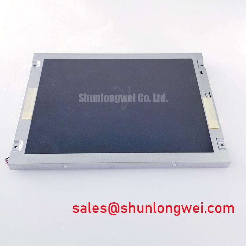
Begin incoming inspection with a full-screen test pattern rather than a single logo or menu page. Solid white, black, red, green, and blue fields help expose stuck pixels, uneven illumination, edge shading, and localized bright or dark areas. Inspect the screen from the normal operator position and from modest horizontal and vertical angles, because a panel that appears acceptable on a bench may reveal nonuniformity after it is installed behind a machine bezel.
The supplied official data identifies the NL6448BC26-27D as a TFT-LCD display module, but it does not state the backlight technology, luminance rating, optical uniformity, contrast ratio, dimming method, L70 or B50 life value, or chromaticity tolerance. The system integrator should verify these items from the original panel documentation. Do not assume that a controller configured for one backlight arrangement can be connected to another without checking the panel and driver requirements.
For an industrial HMI, brightness control should be checked across the complete operating range. If the host uses PWM dimming, the display engineer should verify the selected frequency, duty-cycle response, and control polarity against the backlight driver documentation. The purpose of this test is to identify visible flicker, audible interaction with the driver, unstable low-brightness operation, or a nonlinear change in perceived luminance. These are system-level integration checks, not published factory specifications for this model.
Thermal inspection is also useful during a powered bench test. Observe the narrow display edges, connector region, and adjacent mounting surfaces for localized heating. A chassis design should distribute mechanical support without blocking intended heat paths. Any proposed aluminum spreader rail, ventilation feature, or bezel modification must be assessed against the actual mechanical drawing and the panel manufacturer’s restrictions. Internal optical materials and their aging behavior should not be inferred without documented source data.
For replacement work, record the appearance of the known-good panel before removal. Capture photographs of the white and black fields, note the brightness setting, and preserve the host configuration. This gives the repair team a practical comparison when evaluating the replacement without attributing every visible difference to the LCD module itself.
VESA or JEIDA Data Mapping and Even/Odd Channel Signal Integrity
After the optical inspection, verify the connector keying, pin order, cable direction, and locking condition with power removed. The NL6448BC26-27D specification context supplied for this page does not confirm whether the interface is LVDS, TTL, or another display signaling arrangement, and it does not state the logic supply voltage, pixel clock range, data mapping, or timing limits. The system integrator should verify the required interface and supply voltage from the original panel documentation rather than selecting a controller by model name alone.
When the host uses a differential display interface, the engineering objective is to preserve the intended characteristic impedance and maintain closely coupled differential routing through the connector and cable transition. The PCB designer should follow the controller and panel documentation for the interface impedance target, pair polarity, termination method, and allowable skew. These are design considerations for the complete display path and are not official factory specifications supplied for this model.
Incorrect JEIDA or VESA mapping can present as abnormal color, split-screen content, swapped data groups, or a picture that appears synchronized but contains incorrect grayscale information. If the replacement powers up with an unexpected image, compare the known-good unit using the same cable and controller. Then verify data mapping, pixel order, clock polarity, enable timing, and controller register settings. This avoids treating a configuration mismatch as an immediate panel failure.
Power sequencing should be checked with an oscilloscope at the panel connector while the host starts and stops repeatedly. Confirm the order and timing requirements stated in the original panel documentation, including logic supply behavior, display enable control, reset behavior where applicable, and backlight activation. The supplied data does not establish a numerical rise-time window for this model, so any timing value must come from the relevant factory documentation or the approved controller design.
In a CNC operator panel or robot teach pendant, cable movement can gradually change contact resistance or introduce intermittent signal behavior. Route the cable so that it is not sharply folded at the connector and so that the locking feature remains fully engaged after the bezel is fitted. A replacement option such as NL10276BC16-06 should be evaluated only after confirming its documented size, interface, resolution, connector, and electrical compatibility with the original assembly.
Chassis Fastener Loading and Optical Mura Control
Mechanical inspection should begin with the enclosure opening and mounting pattern. The official context provided here does not list the panel outline, active-area dimensions, mounting-hole locations, bezel envelope, or approved fastener specifications. Measure the removed panel and compare it with the replacement drawing before tightening any hardware. Even a small mismatch in the opening or support points can place uneven load on the display perimeter.
Use a cross-pattern tightening sequence when the chassis design requires multiple fasteners. The torque value must be taken from the panel drawing, equipment service manual, or approved mechanical specification; the commonly used value for a particular fastener size must not be presented as an NEC factory limit for the NL6448BC26-27D. Mechanical force should be sufficient to secure the module while avoiding localized frame distortion. The final result should be checked with the panel unpowered and powered, because pressure-related optical changes may become more visible on a uniform dark or gray test field.
Optical mura can be difficult to separate from backlight nonuniformity, viewing-angle behavior, cable problems, or host image processing. Test the panel before final enclosure assembly, after initial fastening, and after the machine bezel is installed. If a dark region appears only after tightening, release the mechanical load under controlled conditions and repeat the test. This comparison provides useful evidence without assigning a single cause before the assembly has been examined.
The chassis should also provide a stable reference for the connector and cable. Avoid allowing the FFC or LVDS cable to carry mechanical load, and keep the cable clear of sharp sheet-metal edges. Any gasket, spacer, or bezel insert should be verified against the original construction. Unconfirmed assumptions about light-guide compression, internal optical layers, or adhesive behavior should not be used to define the repair procedure.
🔧 Bench Tip: Disconnect power before inserting or removing the display cable, protect the connector from ESD, and check that the cable is fully square before closing its lock.
Where the display is paired with a separate power or backlight stage, inspect that stage independently for ripple, connector heating, and unstable enable signals. The related NL10276BC30-24D may be reviewed as a separate NEC display solution reference, but its presence does not establish electrical compatibility with the NL6448BC26-27D.
Eye Diagram and Differential Noise Verification in High-Vibration Bays
For equipment installed near variable-frequency motor drives, servo amplifiers, contactors, or switching power supplies, evaluate the complete signal path rather than the LCD module in isolation. Inspect cable routing, shield termination, connector retention, cabinet bonding, and separation from high-current conductors. The NL6448BC26-27D factory context supplied for this page does not include an EMC certification claim, noise-floor limit, eye-diagram limit, vibration rating, or immunity result.
When a display shows intermittent pixels, horizontal bands, or unstable text, compare the symptom with the machine state. Check whether the disturbance changes during motor acceleration, braking, relay operation, or backlight adjustment. Use the known-good signal path as the reference and inspect the display clock and data at the host-to-panel boundary where practical. An oscilloscope or suitable differential probe can help determine whether the problem is associated with signal integrity, power disturbance, grounding, or controller configuration.
Shielding should be implemented according to the equipment EMC design and the cable manufacturer’s construction. A 360-degree shield termination may be appropriate in some enclosure designs, while a pigtail or single-ended arrangement may be required by another system topology. The correct method depends on cabinet bonding, connector design, cable impedance, and the applicable machine-level compliance plan. A discrete display module must not be represented as independently certified to CISPR, EN 55011, or another complete-equipment EMC standard.
Ferrite components can be considered when conducted or radiated interference has been measured, but their impedance characteristics, placement, and effect on signal quality should be validated in the actual harness. Adding a ferrite without checking differential waveform quality can create a new signal-integrity issue. The same principle applies to cable length, connector substitutions, and grounding changes.
Direct sunlight and operator lighting should be included in the optical acceptance test if the panel is used in an exposed control station. The supplied factory data does not confirm a contrast ratio at a stated illuminance level or an anti-glare coating. Verify readability using the original equipment’s viewing window, cover, ambient-light condition, and brightness setting. For broader enclosure and HMI integration considerations, the Industrial Display and HMI Solutions resource can be reviewed alongside the equipment-specific documentation.
Before releasing the panel to production service, retain the inspection record containing the model marking, connector photographs, test-pattern results, host configuration, mechanical observations, and any measured supply or signal behavior. This record supports controlled troubleshooting if the CNC operator panel or robot teach pendant later develops an image, touch-response, or intermittent communication complaint.