

Content last revised on October 25, 2026
Flashlight Dark-Shadow Optical Diagnostic to Isolate Logic vs. Backlight Failure Modes
- Disconnect display power before checking the LB121S03-TL04 label, connector orientation, cable retention, and chassis mounting points.
- Inspect the bezel gasket for displaced sections, trapped debris, and uneven compression before releasing the panel from its enclosure.
- Record whether the fault affects image content, illumination, or both, using the existing controller and a repeatable test image.
- Check for condensation and obstructed ventilation before applying power to an exposed display assembly.
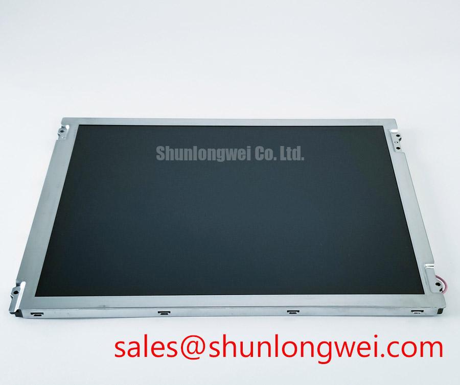
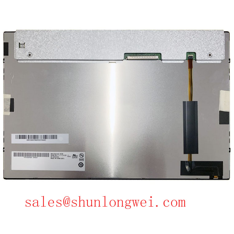
The LB121S03-TL04 from LG Display is a TFT-LCD active matrix color display module for industrial display and HMI integration assessment. Replacement evaluation should connect its electrical interface, mechanical fit, and optical behavior to the equipment’s existing display assembly.
| Product identity | Specification context |
|---|---|
| Model | LB121S03-TL04 |
| Manufacturer | LG Display |
| Product category | Industrial LCD/HMI panel |
| Module construction | TFT-LCD active matrix color display module |
| Electrical, optical, and mechanical ratings | Consult Datasheet for the exact suffix and revision before assigning supply voltage, interface timing, dimensions, or environmental limits. |
Display red, green, and blue full-screen patterns in sequence, recording missing colors, fixed lines, and brightness differences at the same viewing position. As a Design Consideration, repeatable patterns help separate content-dependent artifacts from defects that remain fixed across every image. Keep controller settings unchanged during comparison so that scaling or color adjustments do not obscure the fault.
For a dark screen, direct a flashlight obliquely across the front surface and look for recognizable image content beneath the reflection. A faint image supports further investigation of illumination power, control signals, and connections. It does not establish which backlight component has failed. Fixed lines also require checks of the source signal, connector seating, and panel drive path; their appearance alone does not establish an internal driver fracture.
For viewing-angle assessment, compare the same neutral image from the operator’s expected positions. Contrast shifts and color changes should be assessed directly rather than assigning IPS or MVA characteristics to this model. Measure ambient-light readability through the installed cover window, because reflections from that assembly affect the result. The Winstar Industrial TFT-LCD and OLED Display Modules range provides broader display-selection context; its specifications do not establish this LG panel’s optical performance.
Aluminum Heat Spreader Sizing & Thermal Interface Placement along Narrow Display Edges
Map frame and enclosure temperatures with the display operating at the intended brightness before changing edge cooling. As a Design Consideration, compare temperature distribution after the assembly stabilizes, including the effect of closed covers and restricted airflow. A warmer edge identifies a location to investigate, rather than proving damage to a particular internal optical material.
If the enclosure design uses aluminum heat spreader rails, determine their contact area and placement from the permitted frame contact surfaces and measured heat path. Thermal interface material should not bridge unsupported gaps or introduce pressure against the active display area. Rail dimensions, interface thickness, and attachment loads belong to the enclosure design and should be validated together through temperature and image-uniformity checks.
Trace the illumination power circuit separately from the image interface when reviewing the equipment schematic. The NL6448BC33-24 is another display module to assess in a broader display-system review, rather than a backlight driver for this panel. Its presence in a product comparison does not establish shared power requirements or interchangeable wiring.
Maintenance Note: Periodically inspect ventilation paths and bezel gaskets, restoring airflow and replacing damaged seals without increasing pressure on the display frame.
Backlight maintenance intervals should follow documented operating limits and observed brightness trends. Brightness retention, useful operating life, and statistical failure measures describe different outcomes; they should not be combined into an unsupported service-life claim.
Digital RGB Bus Synchronization & Logic Power Rail Verification
Match the controller connector assignment to the panel connection diagram before evaluating synchronization or changing supply settings. As an Engineering Recommendation, trace supply, return, data, timing, and illumination-control connections through the actual harness. Connector fit alone does not establish electrical compatibility, and the complete model suffix should remain part of the replacement record.
Capture the logic supply and relevant control signals during startup and shutdown. Compare their order and transitions with the panel’s specified sequence, including the relationship between valid image data and illumination enable. A white screen, intermittent image, or shutdown residue can have several causes; correlate the symptom with measured rail behavior and controller output before assigning a fault.
Use routing and decoding checks appropriate to the documented interface. Parallel RGB timing, differential signal integrity, and JEIDA or VESA mapping are distinct checks with different applicability. Applying a differential routing prescription to an unrelated bus does not establish compatibility. Preserve the intended signal-return paths and assess waveform quality at the receiving connection under operating conditions.
When reviewing repair alternatives, compare G121SN01 V2 against the required resolution, connector assignment, supply, timing, mounting envelope, and optical requirements. Treat it as a comparison candidate until those details agree. For a marine radar or navigation bridge console assessment, also verify sunlight readability and protection against moisture and salt exposure at the complete enclosure level.
Chassis Fastener Torque & Bezel Fit to Control Optical Mura
Seat the panel against its intended mounting supports and inspect bezel clearance before tightening the chassis fasteners. As a Design Consideration, uneven gasket compression or distorted mounting surfaces can transmit localized stress into the display assembly. Use the enclosure drawing and fastener joint specification to determine tightening requirements rather than assigning a torque from screw size alone.
Where the mounting arrangement permits, tighten progressively across opposing positions while checking that the frame remains seated without twisting. Compare a uniform gray image before and after assembly to identify mounting-related changes in luminance. If an artifact changes with frame loading, investigate support flatness, gasket placement, and cable interference before increasing clamp force.
Evaluate optical bonding as a separate assembly process involving adhesive compatibility, expansion behavior, and rework constraints. Bonding can change reflections and the internal air gap, but it does not independently establish enclosure sealing. After movement between temperature environments, allow the assembly to stabilize and inspect for moisture before energizing it. The Industrial Display & HMI Solutions resource provides additional context for enclosure and environmental integration.
After final assembly, sweep the equipment’s supported brightness range while observing uniform images and normal text. Correlate visible flicker or audible noise with the actual illumination-control waveform and driver behavior. Any adjustment should remain within the documented panel and driver limits, followed by another check with the enclosure fully closed.