

Content last revised on September 10, 2026
Temperature Window Verification and Sub Zero Liquid Crystal Behaviour
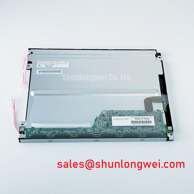
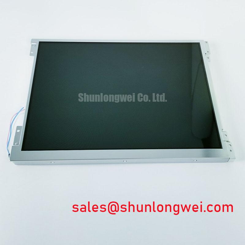
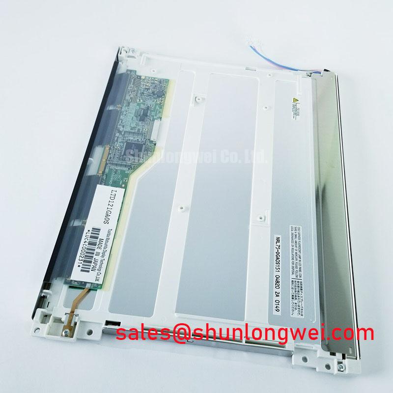
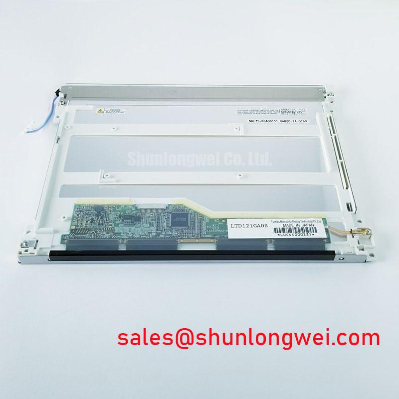
Before applying power, inspect the LTD121GA0S TFT LCD display module for a flat seating surface, intact perimeter sealing, undamaged connector retention, and evidence that the surrounding gasket will not impose uneven pressure on the viewing area. The available official factory information identifies it as an Industrial Grade LCD/HMI Panel in a TFT LCD Display Module format, manufactured under the Toshiba / Samsung designation.
| Official Specification Item | Factory Information |
|---|---|
| Model | LTD121GA0S |
| Manufacturer | Toshiba / Samsung |
| Product Category | Industrial Grade LCD/HMI Panel |
| Module Format | TFT LCD Display Module |
| Specification Status | Official Factory Spec Verified |
For an LCD replacement assessment, the installation team should verify the original equipment temperature limits from the panel documentation and the host equipment service record before treating the module as suitable for any thermal duty. Liquid crystal response can slow at low temperature, while thermal cycling can place mechanical stress on the module perimeter, bezel interface, and sealing materials. These are Design Considerations, not published operating limits for the LTD121GA0S.
During a controlled service test, allow the display assembly to stabilize at the intended ambient condition before judging motion rendering, grayscale transitions, or image persistence. A slow image change can be associated with temperature, source timing, supply behavior, or the panel itself. Comparing the same video input against a known good display path helps separate these possibilities without assigning a single cause.
Signal timing also deserves attention when the terminal is exposed to changing cabinet temperature. The system integrator should verify transmitter clock stability, data hold behavior, connector contact condition, and the original panel interface requirements from the host documentation. Avoid assuming a TTL or LVDS electrical standard solely from the panel family or connector appearance.
⚠️ Maintenance Note: Inspect enclosure gaskets and cooling air paths during scheduled service because poor gasket contact or blocked airflow can increase condensation risk and create uneven mechanical loading around the display aperture.
Backlight Architecture Verification for Ignition and Dimming Service
Backlight diagnosis should begin with identification of the original display assembly architecture rather than substitution of a presumed inverter or driver type. The supplied factory information confirms the TFT LCD module category but does not identify the backlight technology, lamp count, striking requirement, dimming method, or brightness rating for LTD121GA0S. The system integrator should verify the required backlight supply and control conditions from the original panel documentation.
If the host equipment uses a high voltage fluorescent lamp inverter, cold start behavior, connector insulation condition, return path integrity, and inverter protection status should be checked with suitable service instrumentation. If it uses an LED driver, technicians should instead verify the driver enable path, dimming control, output connection, and thermal contact of the complete lighting assembly. Neither architecture should be attributed to this exact model without the applicable factory document.
Audible noise, intermittent illumination, or a dark image with an active video signal can arise from more than one portion of the display chain. Inspecting the power rails, backlight control signal, cable seating, and the controller board condition provides a more reliable repair sequence than replacing a single element based on one visible symptom. For adjacent display solution comparisons, the NL10276BC30-18 page can be reviewed as a separate module reference, subject to interface and mechanical verification.
Pixel Jitter and Horizontal Noise Control Near Motor Drive Equipment
When pixel instability or horizontal bands appear in a control cabinet, first inspect the display cable route, grounding continuity, connector latch engagement, and cable damage near switching equipment. Motor drives can create a demanding electrical environment, particularly where power and display harnesses share an enclosure or routing channel. The relationship between drive control systems and position feedback is illustrated in this rotary encoder reference, while high current switching environments are also discussed in this welding power supply reference.
A Design Consideration is to keep the display signal path physically separated from motor output conductors where the equipment layout permits, while preserving the original grounding concept. Shield termination, common mode suppression, chassis bonding, and cable routing must be validated at system level because their effectiveness depends on the complete enclosure, source board, cable assembly, and drive installation.
Do not assume that a visible line proves panel failure. It can indicate a video source issue, an interface timing disturbance, an impaired cable shield, a connector problem, or a display fault. Verify the signal path with a known good assembly or appropriate measurement equipment before making a module level decision. Engineers evaluating related screen formats can compare the separate LQ10D321 listing, while confirming every electrical, optical, and mechanical requirement independently.
Edge Thermal Management and Optical Surface Preservation
Mount the LTD121GA0S so that the chassis supports the module evenly and does not concentrate force at one bezel edge. Uneven fastening, warped brackets, and compressed sealing material can contribute to localized pressure marks or nonuniform appearance. The module mounting pattern, bracket geometry, and tightening sequence should follow the original equipment mechanical documentation because no official mounting torque or dimensional data is provided here.
Thermal management of the full display assembly is also a Design Consideration. Where an enclosure has limited air exchange, technicians should inspect heat spreading surfaces, ventilation paths, cable strain relief, and any contamination accumulated around the panel perimeter. These checks help preserve stable conditions for the display system without asserting an unverified backlight construction or lifetime rating for this model.
For applications that require a structured environmental assessment, including industrial HMI and monitoring installations, consult Industrial Display & HMI Solutions as a service and integration reference. High precision surgical navigation and ultrasound diagnostic terminals should only be evaluated as potential applications after the system owner confirms the applicable image performance, electrical interface, enclosure, and regulatory requirements.