


Content last revised on September 10, 2026
Mitigating Gray to Gray Response Time Escalation during Cold Start Machine Power Up
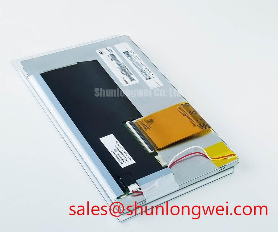
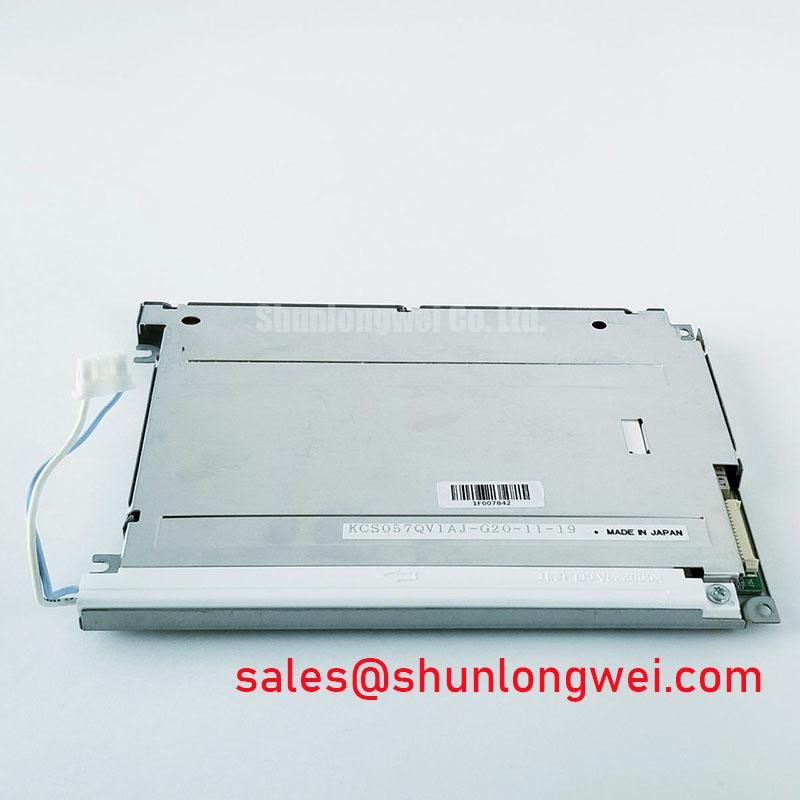
Before connecting the KCS057QV1AJ-G23, compare the module label, mechanical outline, connector position, and original equipment display documentation with the removed panel while all power sources are isolated. This Kyocera unit is identified as an Industrial Grade LCD/HMI Panel in a TFT-LCD Display Module enclosure. The available verified factory information does not establish its interface voltage, signal format, native resolution, optical values, backlight electrical requirements, operating-temperature rating, or viewing-angle specification; these items must be checked against the original panel documentation before replacement integration.
| Item | Verified Information |
|---|---|
| Model | KCS057QV1AJ-G23 |
| Manufacturer | Kyocera |
| Product category | Industrial Grade LCD/HMI Panel |
| Module form | TFT-LCD Display Module |
| Specification status | Official Factory Spec Verified |
At a cold start, begin by observing whether the display image becomes stable only after the enclosure temperature rises. Liquid-crystal response can slow at low ambient temperature because the fluid behavior changes, but no gray-to-gray response time or operating-temperature range is confirmed here as an official specification for KCS057QV1AJ-G23. A sluggish transition, temporary ghosting, or delayed image settling therefore requires comparison with the original panel documentation and with a known-good system where available.
As a Design Consideration, separate panel behavior from upstream timing problems. Check the host power sequence, panel-enable timing, image-data integrity, and backlight-control state before attributing a cold-start symptom to the LCD itself. A controller that applies image data before its supply rails and enable states have settled can create symptoms that resemble low-temperature optical lag. The system integrator should verify the required supply voltage and power sequencing from the original panel documentation.
Perimeter sealing and the mechanical restraint imposed by the surrounding bezel also deserve inspection after repeated thermal exposure. Look for an uneven clamp line, distortion at the display border, or a localized change in luminance after the unit reaches its normal enclosure condition. These observations are inspection points, not evidence of a defined temperature qualification for this specific module.
LED-backlight maintenance should be evaluated through actual brightness measurements and the original equipment maintenance criteria. A frequently cited light-output point expressed as a percentage after a stated operating duration is not an official lifetime rating for this model unless it appears in the applicable Kyocera documentation. Constant-current driver stability, thermal path quality, and controlled dimming behavior should be examined together. For broader environmental validation practices used around industrial operator interfaces, see Industrial Display & HMI Solutions.
Industrial Bezel Mechanical Envelope Tolerances and Mounting Screw Torque Optimization
Place the unpowered module into the intended bezel opening without tightening fasteners, then verify that no edge, gasket, cable bend, or rear support applies point pressure to the active area. A mechanical mismatch can appear as a bright edge, a local dark field, or a pattern visible only on uniform gray content. Such evidence should lead to an enclosure and mounting review rather than a quick conclusion about panel optics.
The official information available for KCS057QV1AJ-G23 identifies its module category and enclosure type, but it does not provide verified screw locations, bezel dimensions, allowable compression, or fastening torque. The original mechanical drawing remains the controlling source for these requirements. Where an M3 fastener is actually specified by the panel drawing and host structure, use a controlled fastening torque appropriate to the approved fastener, thread engagement, materials, and host structure; this is not a Kyocera factory torque rating for this part.
Tighten any approved mounting points in a cross pattern and inspect a white, gray, and black test image after each installation stage. This process helps reveal local stress before the equipment returns to service. 💡 Pro Tip: Do not use the display bezel to correct a warped chassis opening, because uneven clamping can create optical nonuniformity that is difficult to distinguish from a panel fault.
Backlight performance and mounting stress should not be treated as independent issues. A distorted mechanical stack can alter heat dissipation and lead to inconsistent visual observations during a service check, yet it does not prove a specified LED-life outcome. Verify the rear clearance, ventilation path, and original retention scheme as a complete assembly.
Industrial EMI Noise Immunity, Chassis Shielding Continuity and Common Mode Ferrite Chokes
If horizontal bands, intermittent pixel disturbance, or image jitter occur only when adjacent motor-control equipment operates, inspect the complete signal path before changing the panel. Confirm connector engagement, cable routing, chassis bonding continuity, and the relationship between the display cable and high-energy conductors. The available verified information does not identify the electrical interface of KCS057QV1AJ-G23; the system integrator must verify whether the original equipment uses LVDS, TTL, or another signaling arrangement from the panel documentation.
For an interface documented as LVDS, differential-pair routing should preserve pair symmetry and minimize exposure to common-mode noise. For a documented TTL connection, signal return continuity and reference integrity become especially important. The selected mapping must also match the host’s documented JEIDA or VESA data arrangement where that format applies. A format mismatch can produce abnormal colors or image ordering, while noise coupled into a valid path can present as unstable horizontal artifacts; an oscilloscope comparison against a known-good signal path is more reliable than visual diagnosis alone.
Shield termination and common-mode ferrite selection are Design Considerations for the finished equipment, not certified characteristics of this LCD module. A shielded cable can be useful only when its termination scheme is compatible with the chassis and controller architecture. Any change should be validated under representative drive operation while checking image stability and peak signal margins. This component-level discussion does not establish system EMC compliance.
Kyocera’s silicon nitride substrates for power modules describe a separate power-semiconductor product area. They should not be used to infer the construction, insulation properties, thermal capability, or electrical specifications of this LCD display module.
Super IPS or MVA Wide Symmetric Viewing Cone Assessment for Multi Angle Consoles
The verified information for KCS057QV1AJ-G23 does not identify its LCD mode as Super IPS, MVA, or TN, and it does not confirm a symmetric 85°/85°/85°/85° viewing cone. Do not select a replacement based on those characteristics without the original Kyocera optical specification. Inspect the installed panel from the actual operator positions with representative screen colors, grayscale fields, and dark content.
Grayscale inversion, contrast shift, or color change viewed from an angle can arise from the panel mode, polarizer orientation, host image settings, or an optical stack issue. A useful field check is to observe whether the condition follows the viewing position, remains fixed to one region of the screen, or changes with the displayed pattern. This narrows the inspection path without claiming a single cause.
Surface anti-glare treatment, contrast ratio, sunlight readability, and brightness retention are likewise not confirmed official specifications in the provided data set. When an industrial console operates under strong ambient illumination, designers should evaluate the original panel’s optical data together with the enclosure window, glare geometry, display orientation, and permitted backlight operating conditions. For heavy earthmoving-equipment telematics displays, vibration restraint and viewing position are potential compatibility considerations, subject to confirmation of the host mechanical and electrical documentation.