





Content last revised on September 13, 2026
Industrial Bezel Mechanical Envelope Tolerances and Mounting Screw Torque Optimization
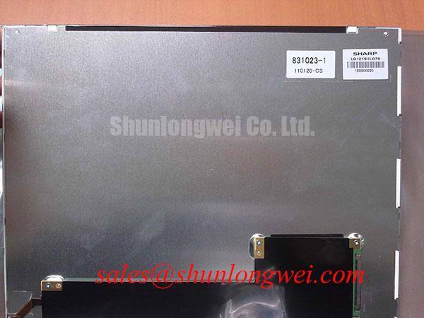
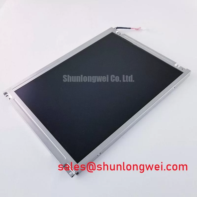
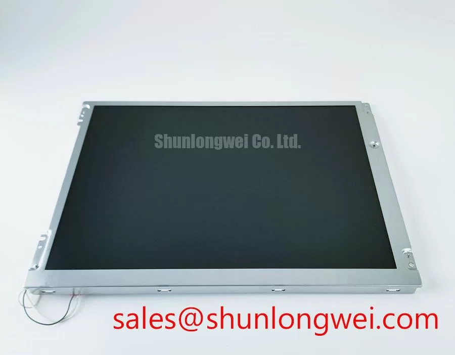
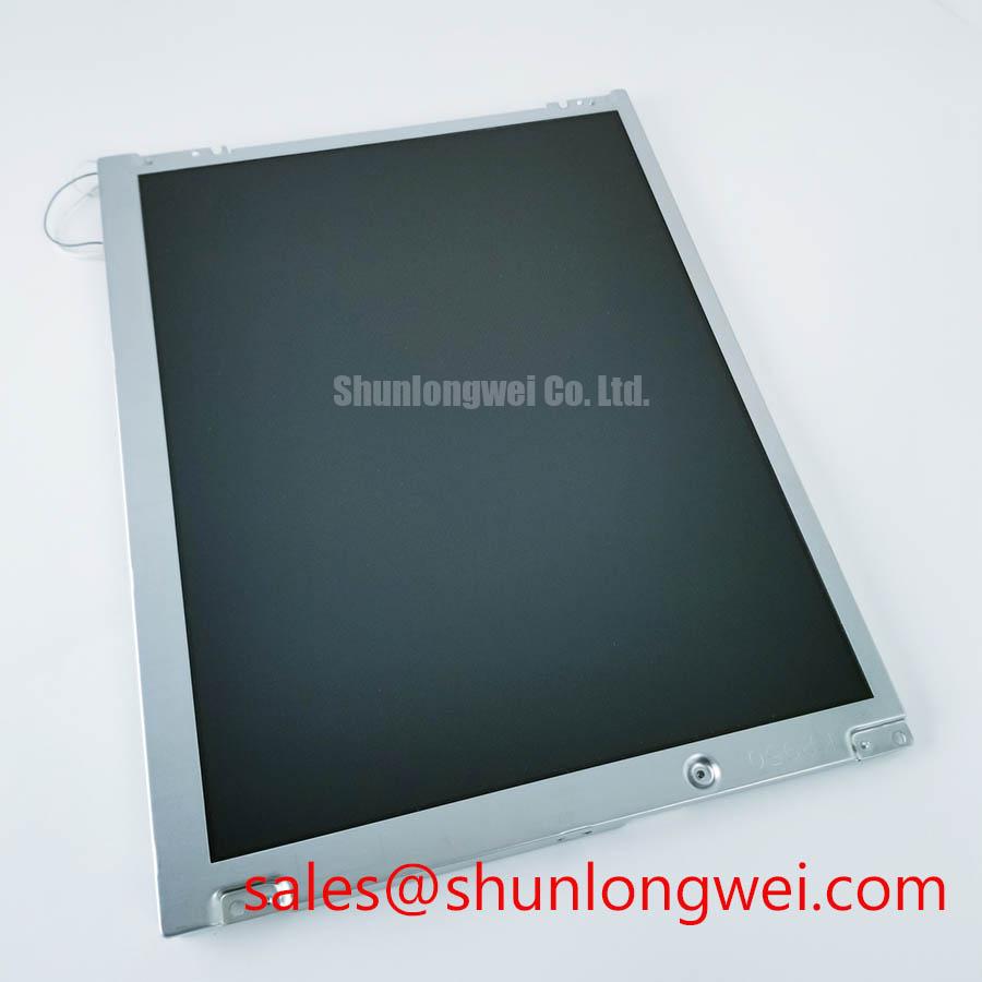
When a dark area, uneven luminance, or a pressure mark appears after installation, begin with the mechanical envelope rather than immediately changing the controller board. Remove the panel from the bezel and inspect whether the frame is twisting, whether a cable is trapped behind the module, and whether a fastener is contacting the display assembly. The factory information supplied for LQ121S1LG45 does not publish the panel’s outer dimensions, bezel clearance, mounting-hole geometry, or approved screw torque. Those values must be taken from the original Sharp mechanical drawing or the equipment manufacturer’s service documentation.
As a Design Consideration, the bezel should support the module evenly without transferring concentrated force to the active display area. Check the chassis for burrs, distorted brackets, compressed gaskets, and uneven screw seating. If the system uses M3 fasteners, the maintenance team should use the equipment maker’s specified torque and tighten progressively in a cross pattern. The often-used industrial starting range of 0.35 to 0.45 N·m is a general mounting reference only, not an official specification for this Sharp model. Final torque remains dependent on the bracket material, thread engagement, washer arrangement, and panel construction.
Do not assume that optical nonuniformity is caused by the LCD itself. A bezel opening that is too small, a mounting boss that is too high, or a screw tightened against the wrong frame layer can create localized stress and visible mura. Release the mechanical load, reinstall the module without the signal cable being folded sharply, and compare the image before and after final fastening. If the defect changes when the frame is relieved, the result should be treated as a mechanical integration issue requiring dimensional correction.
For a navigation bridge console exposed to strong ambient light and salt-laden air, enclosure sealing and service access also need review. The display module should be protected by the host enclosure design, while ventilation and condensation control must be evaluated at system level. The product data supplied here does not assign an independent salt-fog rating, ingress rating, or marine approval to the panel.
During a replacement audit, the LMS700KF01-001 may be evaluated as a separate same-size-class or same-resolution-class service option, but its electrical and mechanical compatibility must be confirmed independently rather than assumed from appearance.
Backlight Inverter and Ignition Troubleshooting
Backlight troubleshooting should begin at the host equipment’s backlight supply and control path. A black display with a visible image under angled light can point toward a backlight or inverter path, while a completely blank image requires separate checks of logic power, video data, timing control, and panel condition. These observations are useful for narrowing the test sequence, but they do not identify a single failed part without electrical measurement.
The supplied official product information does not confirm whether LQ121S1LG45 uses a CCFL backlight, an LED backlight, a dual-channel inverter interface, a specific striking voltage, a dimming method, or a rated service-life figure. Do not apply a CCFL ignition voltage to this module unless the original panel documentation explicitly requires an external CCFL inverter and identifies the correct lamp connections. Likewise, do not connect a constant-current LED driver to an unverified panel.
For a suspected CCFL system, the technician should first identify the inverter board, lamp connectors, enable line, dimming line, and protective shutdown behavior from the equipment schematic. High-voltage probing requires an appropriately rated differential probe and a controlled test procedure. A failed start attempt may result from the inverter, lamp circuit, enable timing, connector contact, or protection feedback. Inspecting only the lamp output is not sufficient.
For an LED system, confirm the driver input, enable state, current regulation, and dimming control according to the original assembly documentation. PWM dimming performance, acoustic noise, thermal distribution, and luminance uniformity belong to the complete display and driver combination. A 1000 to 1 dimming ratio or a greater-than-50,000-hour half-life must not be attributed to LQ121S1LG45 without a model-specific source.
High-frequency inverter wiring can couple noise into the display signal path. As a Design Consideration, keep high-voltage backlight wiring physically separated from logic cables, avoid unnecessary loop area, and bond shields according to the host equipment’s EMC strategy. The system integrator should verify differential routing, return-current paths, and conducted noise during actual inverter operation. The related LQ9D03B can be reviewed as a separate display solution component when the host design requires a compatible topology, but it is not presented here as a confirmed accessory for this Sharp module.
⚠️ Field Alert: Disconnect system power and allow the backlight circuit to discharge before removing or inserting display and inverter connectors.
Display Interface, Timing, Pixel Clock, and Skew Compensation
Before measuring video timing, photograph the existing cable orientation and record every connector marking. The official information supplied for LQ121S1LG45 does not specify a 20-pin or 30-pin connector, LVDS lane count, TTL input, JEIDA mapping, VESA mapping, pixel clock range, logic supply voltage, power sequencing, or data hold-time limits. A connector that physically mates can still carry an incompatible signal arrangement, so pin position must be verified against the panel documentation.
When the panel is connected to a replacement controller, inspect the system power rail with an oscilloscope rather than relying only on a multimeter. The correct voltage, rise-time behavior, reset relationship, display-enable timing, and backlight-enable sequence are determined by the original panel and controller design. Do not select between 3.3 V and 5.0 V based on connector appearance. The system integrator should verify the required supply voltage from the original panel documentation.
Split images, missing color groups, unstable synchronization, or intermittent vertical lines may indicate a mismatch in data mapping, lane order, clock relationship, cable contact, or signal integrity. Compare the suspect path with a known-good controller and cable where available. An oscilloscope can help establish whether the clock and differential data remain stable at the panel connector, but the measured waveform must be judged against the applicable Sharp timing limits rather than a generic threshold.
As a Design Consideration, differential pairs should be routed as controlled-impedance structures with a continuous return path and minimal branch stubs. The commonly used 100-ohm differential target applies to many high-speed display links, but it is not confirmed here as an official electrical specification for this model. Pair length matching, connector quality, cable shielding, and clock-to-data skew should be validated under the actual enclosure and servo-noise conditions. If the display is installed near a radar processor, motor drive, or switching power converter, test the image while those neighboring systems are operating, not only during a quiet bench test.
Gamma correction and grayscale voltage behavior are controlled by the panel and timing controller combination. If grayscale steps appear compressed, colors are inverted, or the image changes after a controller replacement, verify the controller firmware, panel profile, gamma configuration, and timing table. Do not rewrite gamma values or power sequencing parameters without the original system reference, because a visually acceptable result at room temperature may become unstable across the equipment’s operating range.
Polarizer Surface and Optical Film Inspection under Direct Industrial Lighting
Inspect the polarizer surface under diffuse light before powering the module. Look for scratches, pressure marks, edge lifting, contamination, and irregular reflections, then compare the surface with the old panel under the same viewing angle. The supplied factory data does not identify the optical mode as TN, IPS, or MVA, and it does not specify a symmetric viewing cone, retardation-film construction, anti-glare etch, surface hardness, contrast ratio, luminance, or color uniformity. Those characteristics must be confirmed from the model-specific optical datasheet.
In a bright bridge console, apparent image quality depends on more than the panel’s nominal viewing specification. The cover window, anti-glare treatment, ambient reflections, display angle, backlight level, and operator position all influence readability. If a replacement shows color shift when viewed from above or from the side, compare it with the original module and confirm that the optical mode and viewing direction match the host design. Do not describe the panel as a wide-view IPS or MVA display unless Sharp documentation confirms that classification.
Optical inspection should also include the perimeter seal, frame contact, cable routing, and any protective window. A pressure-related mark may change after the module is released from the bezel, while a surface defect remains visible with the panel removed. Clean the polarizer only with a procedure approved for the installed surface treatment. Avoid aggressive solvents, dry wiping, and concentrated pressure, especially when field dust or salt residue is present.
For marine equipment evaluation, enclosure sealing, condensation management, cleaning chemicals, and direct sunlight exposure should be tested as part of the complete console. The panel’s official factory data supplied for this page does not establish independent marine certification, EMC compliance, salt-fog resistance, or a guaranteed lifetime under a specified thermal profile. Engineers should verify those requirements at system level before approving the display for continuous service.
When a display replacement must be qualified quickly, record the original image settings, connector identification, backlight behavior, bezel dimensions, and controller configuration before removal. The Industrial Display and HMI Solutions resource provides broader integration context for harsh-environment display work, while final approval for LQ121S1LG45 remains dependent on the original equipment documentation and measured compatibility.