Content last revised on October 11, 2026
Dark-Field Stability and Grayscale Behavior During Warm-Up
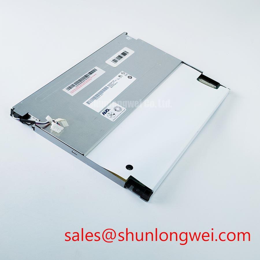
When a surgical navigation or ultrasound display shows a dark field, unstable grayscale, or intermittent image, first separate the fault domain: confirm the panel supply at the system connector, observe the backlight response, and reseat the display cable only after power has been removed. The G104SN02-V0 is an AUO TFT LCD active matrix color display module identified for industrial HMI and display replacement evaluation.
The available product information classifies this part as an Industrial Grade LCD/HMI Panel. It does not establish a complete electrical interface table, pin assignment, supply voltage, optical rating, or mechanical drawing. Those values must be checked against the model-specific datasheet, original equipment documentation, and panel revision installed in the target display.
- Model: G104SN02-V0
- Manufacturer: AUO
- Product category: Industrial Grade LCD/HMI Panel
- Construction category: TFT-LCD Active Matrix Color Display Module
Dark-field instability should be assessed by comparing a uniform black image, mid-gray ramps, and primary-color screens while the display reaches its normal operating temperature. A grayscale inversion pattern can point toward viewing-angle behavior, timing configuration, or T-CON gamma control, while a localized dark shadow that remains fixed during image changes deserves separate backlight and optical inspection.
For the G104SN02-V0, the panel category confirms an active matrix color display, but the available product information does not certify a specific TN, IPS, or MVA optical structure. Do not transfer viewing-cone figures from another AUO family into this replacement decision. In a medical display enclosure, assess grayscale uniformity from the intended operator position and check whether ambient light changes the perceived black level or reveals surface haze.
Optical acceptance should be defined at system level. When direct sunlight is part of the installation, evaluate ambient contrast under representative lighting conditions rather than treating a dark-room contrast rating as a sunlight-readability guarantee. Surface anti-glare behavior also requires physical inspection because etching, cover glass, protective film, and enclosure geometry can change reflections independently of the LCD cell.
Temperature tracking matters when a display moves from a cold standby condition into continuous operation. Watch the same grayscale patches during warm-up and compare them with a known-good image path. If the image changes across the entire panel, review T-CON timing, gamma reference behavior, and supply stability. If the change remains confined to one area, inspect the optical stack and edge connections before changing the host controller.
Shielded FFC and FPC Grounding Across Connector Shells
Pixel jitter and horizontal noise bands near variable-frequency motor drives are best investigated by tracing the display cable route from the host board to the panel connector. Keep the cable away from high-current switching conductors, check the connector seating force, and inspect any shield termination at both ends without assuming that the display module itself contains a specified EMC filter.
The available G104SN02-V0 product information does not include a verified LVDS or TTL pin map. The system integrator should therefore match the replacement against the original cable keying, signal order, power pins, enable signals, and panel timing configuration. An apparently compatible connector can still carry a different pin assignment or power sequence.
For a differential video interface, controlled pair routing and a continuous return path are Design Considerations. Many LVDS systems use a nominal 100 Ω differential environment, but the correct target belongs to the transmitter, cable, receiver, and connector combination rather than to the LCD model name alone. Confirm the signal eye and clock stability at the receiving end with the installed cable, especially when the display is mounted close to a 400 V motor drive.
| Item | G104SN02-V0 | G121SN01-V1 |
|---|---|---|
| Manufacturer | AUO | AUO family reference |
| Product category | Industrial TFT-LCD active matrix color module | Separate model requiring interface and mechanical compatibility review |
| Mechanical compatibility | Verify against the model-specific outline drawing | Do not assume interchangeability from model naming |
| Engineering action | Match panel revision, connector, timing, and enclosure geometry | Review the dedicated G121SN01 V1 product information before any substitution decision |
When the display shares a cabinet with an inverter, common-mode current can enter through cable shields, mounting metalwork, or the host ground. A ferrite component may be considered only after identifying the noise path and checking its effect on the video edge quality. It should not be treated as a standard accessory of this AUO panel.
⚠️ Field Alert: Disconnect system power before inserting or removing the FFC or FPC connector to avoid stressing signal and power contacts during a live connection.
Incoming Benchtop Inspection: COG and TAB ACF Integrity
Use a controlled three-screen check before installing the replacement into the equipment: full red, full green, and full blue. These screens expose line defects, color-channel interruptions, and uneven illumination more clearly than a complex medical image. Record whether a defect follows the image content, remains fixed on the glass, or changes when the backlight level changes.
A 45-degree flashlight inspection is useful for separating a dark optical region from a display-drive defect. With the panel unpowered, use oblique light to look for pressure marks, edge damage, contamination, or irregular reflections around the glass perimeter. During powered testing, a dark region that remains visible across primary colors may require inspection of the backlight and optical layers, while a narrow line or repeated column pattern may require review of the COG or TAB bonding area, depending on the panel's construction.
Do not press the glass, bonded edge, or flexible tail while testing. Mechanical pressure can temporarily alter an intermittent connection and make the fault appear resolved. The correct approach is to compare the symptom with a known-good signal source, inspect connector retention, and monitor whether the defect changes after controlled temperature exposure within the documented operating limits.
Clock jitter and data hold time belong to the complete video link. If the host uses LVDS or TTL, verify the transmitter configuration, pixel clock, data mapping, and timing margins against the original panel documentation. The active matrix category alone does not define those interface values. A display that powers its backlight but shows no valid image may still have a protocol, enable, timing, or signal-integrity problem.
For industrial HMI sourcing, compare the original panel label, connector orientation, cable length, and mounting pattern before approving a replacement. The G121X1-L04 may be reviewed as a related display solution in the surrounding system, but it should not be treated as a confirmed companion part for the G104SN02-V0 without a complete interface check.
Flush-Mount Open-Frame Bezel Integration and Perimeter Gasket Shock Isolation
Mechanical installation should begin with an unloaded fit check. Place the panel into the bezel without tightening the fasteners, verify that the glass is not bearing against the opening, and confirm that the flexible cable can reach the host connector without a sharp bend. Enclosure planning requires the model-specific outline drawing; a general form-factor description is not sufficient.
A perimeter gasket can distribute enclosure contact and reduce vibration transfer, provided it does not press directly on the active viewing area or bonded edge. The gasket material, compression, and enclosure tolerances are Design Considerations determined by the equipment designer. Localized pressure can appear as mura, corner shading, or a dark field that changes when the bezel is loosened.
Use a cross-pattern tightening sequence for the enclosure fasteners and stop if the image changes during mechanical assembly. The available product information does not define an official M3 torque limit for this model, so the final value must come from the applicable panel mounting instructions, chassis drawing, fastener specification, and gasket design rather than from a generic panel assumption.
For high-precision surgical navigation or ultrasound diagnostic displays, evaluate the panel with the actual front cover, ambient lighting, and image-processing chain installed. This application discussion does not establish medical certification or suitability for a particular diagnostic system. AUO’s industrial display information provides broader manufacturer context, while practical optical assessment should also consider diffuser behavior and brightness-enhancement films described in this optical reference. Additional panel integration principles are available in The Ultimate Guide to Industrial TFT LCD Technology.
Before release to service, verify image uniformity after the bezel is fully secured, confirm that the backlight remains stable at the intended brightness, and check that cable routing does not introduce intermittent noise when nearby equipment starts or stops. For medical equipment, also follow the equipment manufacturer's replacement and validation procedures.