Content last revised on September 29, 2026
What This Component Is and Its Industry Significance
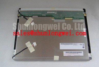
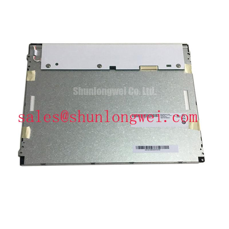
In industrial automation, machine control, and mission-critical instrumentation, the human-machine interface (HMI) serves as the primary bridge between human operators and complex mechanical or electrical processes. Within this domain, the 12.1-inch SVGA (800 × 600 pixels) display module has long stood as an industry-standard form factor. Manufactured by AU Optronics (AUO), the G121SN01 family represents one of the most widely deployed industrial liquid crystal display series. Specifically, comparing the earlier AUO G121SN01 V1 and the modernized AUO G121SN01 V4 highlights the broader technological evolution of industrial Liquid Crystal Display Technology over the past two decades.
Industrial displays differ substantially from commercial consumer-grade panels. While consumer displays prioritize razor-thin bezels and rapid product turnover cycles, industrial displays must deliver continuous 24/7 operation, extended operational lifespans (frequently exceeding 50,000 operating hours), resistance to wide temperature fluctuations, mechanical shock, and electromagnetic interference (EMI). The original AUO G121SN01 V1 addressed these requirements using Cold Cathode Fluorescent Lamp (CCFL) illumination paired with an amorphous silicon (a-Si) thin-film transistor matrix. As solid-state lighting matured, AUO introduced the G121SN01 V4, migrating the platform to an energy-efficient White Light-Emitting Diode (WLED) backlight system with integrated driver circuitry and an expanded operating temperature window.
The significance of understanding these two revisions lies in system lifecycle maintenance, legacy equipment retrofitting, and new embedded hardware architecture. Design engineers and field technicians regularly encounter scenarios where aging CCFL-based displays in legacy machine tools, medical carts, or marine navigation consoles must be maintained, repaired, or upgraded. Upgrading from the G121SN01 V1 to the G121SN01 V4 is not always a direct drop-in procedure due to differences in backlight driving voltages, inverter requirements, pin configurations, and optical characteristics. Similar migration challenges and form factor decisions are common when evaluating other legacy-to-modern display modules, such as the NL6448BC26-27 or specialized flat-panel units like the EL552-256-Q1.
Figure 1: Functional Block Topology of Modern Industrial TFT-LCD Systems
Working Principle, Pixel Architecture, and Optical Subsystems
Both the AUO G121SN01 V1 and G121SN01 V4 rely on transmissive Thin-Film Transistor Liquid-Crystal Display (TFT LCD) technology. To understand their operational differences, one must first examine how a standard industrial TFT panel controls light transmission at the subpixel level, followed by the physical differences in their respective illumination sources.
Active Matrix Switching and Liquid Crystal Modulation
An active-matrix TFT display functions as an array of microscopic, voltage-controlled optical shutters. The panel comprises several distinct layers laminated together:
- Rear Polarizer: Linearly polarizes the unpolarized light emitted by the backlight unit.
- TFT Glass Substrate: Contains an array of three-terminal amorphous silicon transistors arranged in rows (gate lines) and columns (source/data lines). Each subpixel corresponds to an individual TFT that acts as an electronic switch.
- Liquid Crystal (LC) Layer: Formed of nematic liquid crystal molecules sandwiched between transparent Indium Tin Oxide (ITO) electrodes. In the unenergized state (Twisted Nematic mode), the molecular alignment naturally rotates the polarization plane of light by 90°.
- Color Filter Substrate: Features red, green, and blue (RGB) optical filters aligned precisely over each subpixel, complemented by a black matrix to prevent light leakage between adjacent cells.
- Front Polarizer: Oriented perpendicularly (90°) to the rear polarizer.
When the gate driver asserts an active voltage on a row line, the channel of the TFT conducts, allowing the data voltage from the source driver to charge the subpixel storage capacitor (Cst) and the liquid crystal capacitance (Clc). The resulting electric field across the liquid crystal layer forces the rod-like LC molecules to untwist and align parallel to the field. As the molecular twist decreases, the degree of polarization rotation is reduced proportionally. Consequently, light passing through the liquid crystal layer is blocked by the front analyzer in varying degrees, creating precise grayscale gradations from full transmission (white) to total extinction (black).
Backlight Mechanisms: CCFL vs. WLED Architecture
The fundamental physical divergence between G121SN01 V1 and G121SN01 V4 lies in how backlight illumination is generated, regulated, and optically coupled into the light guide plate (LGP):
- G121SN01 V1 (CCFL): Employs cold cathode gas-discharge lamps. Generating light requires an external high-voltage AC inverter that steps up a DC supply (typically 12V) to an ignition strike voltage exceeding 1,000 Vrms to 1,500 Vrms, stabilizing to a continuous operational voltage between 500 Vrms and 650 Vrms at high frequencies (40 kHz to 80 kHz). CCFL lamps contain low-pressure mercury vapor, which emits ultraviolet radiation when struck by electron discharge, subsequently exciting the phosphor coating inside the tube to yield white light.
- G121SN01 V4 (Solid-State WLED): Uses an array of high-efficiency surface-mount white LEDs arranged along the edge of the light guide. Modern WLED designs eliminate high-voltage transformers and hazardous mercury vapor. The V4 integrates an onboard constant-current boost converter driver, accepting a low-voltage DC input (typically 10.8V to 13.2V) and directly driving the LED strings via low-voltage pulse-width modulation (PWM) or analog current dimming.
Key Technical Specifications, Optical Characteristics, and Generational Comparison
Evaluating the AUO G121SN01 V1 alongside the G121SN01 V4 demonstrates significant generational improvements in power efficiency, thermal resilience, optical contrast, and mechanical simplicity. While both panels share the classic 12.1-inch active area (246.0 mm × 184.5 mm) and SVGA resolution (800 × 600 pixels with an aspect ratio of 4:3), their electro-optical specifications differ in critical operational metrics.
The G121SN01 V4 delivers a higher typical luminance (450 cd/m2 versus 350 to 400 cd/m2 in the V1) and an enhanced contrast ratio of 700:1 (or up to 1000:1 depending on specific production revisions), compared to 500:1 on the V1. Furthermore, the solid-state architecture of the V4 drastically extends the operating temperature envelope, allowing deployment in harsh environments ranging from -30°C to +85°C, whereas the V1 is limited to -10°C to +65°C due to CCFL strike voltage limitations at sub-zero temperatures.
| Specification / Parameter | AUO G121SN01 V1 (Legacy) | AUO G121SN01 V4 (Modern Standard) | Engineering Significance |
|---|---|---|---|
| Diagonal Screen Size | 12.1 inches (30.7 cm) | 12.1 inches (30.7 cm) | Identical active visual area and mechanical mounting footprint. |
| Native Resolution | 800 × 600 (SVGA) | 800 × 600 (SVGA) | Pixel pitch: 0.3075 mm × 0.3075 mm; 4:3 industrial aspect ratio. |
| Backlight Technology | 2 × CCFL (Cold Cathode Fluorescent) | Edge-lit WLED (White Light Emitting Diode) | V4 eliminates mercury, high-voltage inverters, and acoustic hum. |
| Integrated Backlight Driver | No (Requires External AC Inverter) | Yes (Built-in Constant Current LED Driver) | V4 reduces bill of materials and simplifies internal chassis cabling. |
| Luminance (Typical) | 350 – 400 cd/m2 (nits) | 450 cd/m2 (nits) | V4 provides superior legibility in high ambient light environments. |
| Contrast Ratio (Typical) | 500:1 | 700:1 to 1000:1 | V4 delivers deeper black levels and higher graphic clarity. |
| Color Depth & Support | 6-bit LVDS (262,144 colors) | 6-bit / 8-bit LVDS (262K / 16.2M colors) | V4 supports smoother color gradients via 8-bit FRC mode. |
| Operating Temperature | -10°C to +65°C | -30°C to +85°C | V4 enables reliable cold-booting and unconditioned outdoor use. |
| Storage Temperature | -20°C to +70°C | -30°C to +85°C | Expanded survivability under extreme logistical conditions. |
| Backlight Half-Life (L50) | 50,000 Hours (Typical) | 50,000 Hours (Minimum) | WLED provides gradual lumen depreciation without sudden lamp ignition failure. |
| Power Consumption (Total) | ~8.5 W to 10.0 W (incl. inverter losses) | ~4.5 W to 6.5 W (Logic + LED driver) | V4 cuts total power draw by roughly 35% to 50%, reducing internal thermal load. |
When selecting industrial visual hardware, engineers also cross-reference these metrics with alternatives such as the ruggedized TX20D208VM0BAA to balance interface complexity, physical depth, and optical requirements.
Practical System Integration, Drive Electronics, and Environmental Considerations
Successfully integrating or replacing an AUO G121SN01 panel requires careful attention to electrical signal integrity, power distribution, thermal management, and mechanical mounting.
1. LVDS Signal Integrity and Timing Configuration
Both display versions utilize Low-Voltage Differential Signaling (LVDS) via a standard 20-pin receptacle (e.g., Hirose DF19 or equivalent). LVDS uses differential voltage pairs (nominal ±350 mV swing) to minimize EMI and support high data rates over unshielded twisted-pair wiring. Key integration considerations include:
- Impedance Matching: Differential traces on the host PCB must maintain a strict differential impedance (Zdiff) of 100 Ω ± 10% (50 Ω single-ended).
- Intra-Pair Skew: Ensure length matching within each differential pair (e.g., RxIN0− and RxIN0+) to within ±0.15 mm to avoid signal phase distortion at the receiver.
- Color Mapping: The G121SN01 V1 operates strictly in 6-bit LVDS mode, whereas the G121SN01 V4 typically features a format selection pin (often Pin 19 or Pin 20 depending on sub-revision) allowing configuration for standard 6-bit or 8-bit (JEIDA / VESA) data mapping. Ensure the host graphics controller timing corresponds to the SVGA standard pixel clock (~40.0 MHz nominal at 60 Hz refresh rate).
2. Backlight Electrical Conversion (CCFL to WLED)
When replacing a legacy G121SN01 V1 with a G121SN01 V4, the legacy high-voltage CCFL inverter must be completely removed. Connecting high-voltage AC inverter outputs to the low-voltage WLED driver will instantly destroy the LED driver stage and pose severe electrical hazards.
- Power Supply: Connect a clean, regulated DC line (typically 12.0 VDC) to the V4 LED driver input pins.
- Dimming Control: The V4 accepts a Pulse Width Modulation (PWM) signal (frequency typically 100 Hz to 1 kHz, 3.3V or 5.0V amplitude) for brightness dimming. If PWM is unavailable, tie the enable pin (EN) to logic HIGH and the dimming pin (DIM/ADJ) to maximum control voltage to operate at 100% fixed luminance.
3. Thermal and Mechanical Precautions
Although WLED backlights generate significantly less waste heat than CCFL tubes, the localized heat flux at the LED edge-bar requires adequate dissipation paths:
- Chassis Thermal Dissipation: Ensure the display's rear metal bezel makes solid mechanical contact with the system chassis to facilitate conductive heat transfer away from the LED edge-strip.
- Uniform Bezel Clamping: Avoid uneven torque on mounting screws. Asymmetrical mechanical pressure on the panel frame induces optical distortion known as "backlight bleed" or "mura" due to localized micro-bending of the liquid crystal cell gap.
- ESD Protection: Always handle display panels in an ESD-protected workstation (ANSI/ESD S20.20 compliant). Static discharge into the LVDS lines or driver IC chips mounted along the glass edge (Chip-on-Glass / COG) can cause permanent line-defect failures.
Figure 2: LVDS Differential Line Routing and Power Decoupling Practice
Engineering Selection Guidelines, Retrofit Procedures, and Field Diagnostics
When maintaining operating industrial machinery or designing updated control terminals, engineering teams must methodically verify compatibility before executing a panel substitution. The following selection framework, retrofit steps, and troubleshooting diagnostics provide a structured approach to deploying the AUO G121SN01 series.
Retrofit Procedure: Migrating from G121SN01 V1 to G121SN01 V4
Field Diagnostic and Troubleshooting Matrix
The table below provides systematic troubleshooting procedures for common faults encountered during field servicing, installation, or retrofitting of industrial LCD panels.
| Failure Symptom | Probable Root Cause | Diagnostic Test / Verification Step | Corrective Action |
|---|---|---|---|
| Completely Dark Screen (No Image, No Light) | Missing backlight power or unasserted Enable signal. | Measure DC voltage at the LED driver VCC pins with a multimeter; verify BL_ON voltage is > 2.5 VDC. | Restore 12V DC rail; correct backlight control logic state in host firmware or harness. |
| Faint Image Visible Under Flashlight (No Backlight) | Backlight driver shutdown or blown input fuse on panel PCB. | Check the surface-mount fuse near the LED connector for continuity (0 Ω). Measure PWM input pin voltage. | Replace blown fuse if caused by transient overvoltage; ensure PWM duty cycle is > 10% and frequency is within range. |
| White Screen (Backlight On, No Data) | Missing logic supply voltage (VDD) to the TFT array. | Measure voltage across Pins 1/2 and Ground at the LVDS connector (expected: +3.3 VDC ± 0.3V). | Check host power supply regulator, LVDS cable continuity, or reset timing circuit. |
| Scrambled, Flickering, or Tilted Image | Incorrect pixel clock frequency or improper LVDS cable termination. | Verify pixel clock with an oscilloscope (nominal 40.0 MHz for SVGA 60 Hz). Inspect differential eye diagram for jitter. | Adjust host video timing registers (H-sync, V-sync, blanking intervals); replace degraded or unshielded LVDS cabling. |
| False Colors / Solarized Posterized Image | Mismatch in 6-bit vs. 8-bit LVDS mapping (VESA vs. JEIDA standard). | Verify the logic level on the 6/8-bit selection pin (Pin 19 or 20). Check host graphics output formatting. | Tie the selection pin to Ground or 3.3V to match host bit output; align driver settings in host OS. |
| Dim Display at Low Ambient Temperatures | Characteristics of aged CCFL lamp in G121SN01 V1. | Measure ambient temperature and lamp strike current; observe tube stabilization time. | Upgrade display to G121SN01 V4 WLED, which maintains instant-on luminance across -30°C to +85°C. |
By following these diagnostic checks and structural integration principles, engineers can ensure high display reliability, maintain long equipment service lives, and execute seamless display lifecycle migrations across all industrial machine platforms.