Content last revised on October 10, 2026
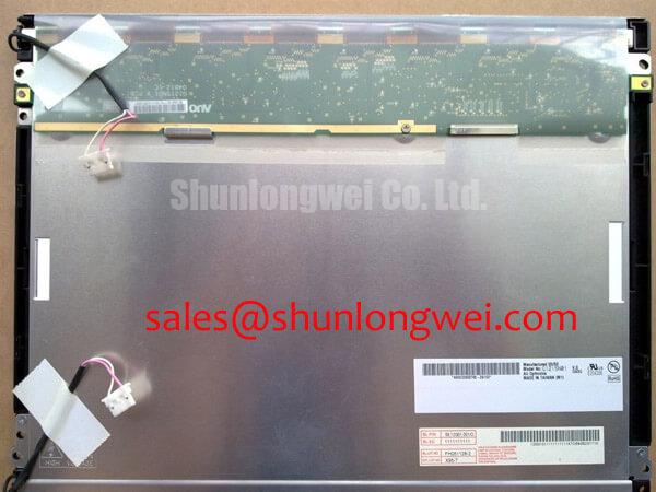
G121SN01-V403 AUO Industrial LCD Display Panel
When a precision test instrument shows a dark screen, first separate the image-generation fault from the illumination fault: operate the panel with a known-good signal path, inspect the display connector with power removed, and use an angled flashlight to check whether faint graphics remain visible. The unit under evaluation is G121SN01-V403, manufactured by AUO as an industrial-grade LCD/HMI panel.
Its documented construction is a TFT-LCD active-matrix color display module. The panel’s model-specific datasheet and host equipment documentation should be consulted together for supply voltage, interface assignment, timing, backlight drive, mounting dimensions, and optical requirements. This distinction matters when replacing a panel in a precision electronic test and measurement instrument, where an apparently similar display can still fail because of connector mapping, timing configuration, or chassis clearance.
Flashlight Dark-Shadow Optical Diagnostic to Isolate Logic vs. Backlight Failure Modes
Use the flashlight test before removing the panel from the instrument. Display a white field, a black field, and a primary-color sequence from the host controller. Hold a flashlight at approximately 45 degrees to the screen surface and look for faint characters, menus, or waveform traces within the dark image. Visible graphics with weak illumination point the investigation toward the backlight path, brightness control, or panel-side power connection; a completely inactive image requires equal attention to the controller, timing path, connector seating, and panel logic.
Run the color sequence at a controlled brightness level and observe whether the fault follows the image content or remains fixed in one region. A stationary dark area can be associated with illumination uniformity, optical obstruction, mechanical pressure, or a local panel defect. A line, block, or intermittent region that changes with flexing should not be treated as a backlight-only problem. Inspect the display without applying bending force, then compare the panel response with the known-good signal path in the instrument.
For high-EMI equipment, differential display routing is a Design Consideration, not an AUO specification for this model. The system designer should preserve controlled differential impedance, matched path geometry, short return-current paths, and appropriate connector shielding according to the actual interface standard. Skew, termination, common-mode behavior, and cable construction must be evaluated against the host controller and measured at the receiving end when image artifacts appear during instrument operation.
Do not identify a COG or driver connection fault from one symptom alone. A narrow line may arise from panel electronics, connector contact, cable stress, controller timing, or mechanical loading. Compare the fault during power-up, static image display, and controlled cable movement while observing the known-good reference path. This approach avoids replacing the G121SN01-V403 before the instrument-level signal chain has been isolated.
For a same-size or same-resolution replacement study, engineers can place NL12876AC18-03 beside the AUO panel in a compatibility worksheet. It should be treated as a reference candidate only; connector pinout, active area, mounting geometry, optical behavior, and controller timing still require a direct comparison.
Aluminum Heat Spreader Sizing & Thermal Interface Placement along Narrow Display Edges
Thermal work around a narrow display edge begins by locating the actual heat source rather than attaching metal directly to the panel. Check the backlight driver area, power conversion components, nearby enclosure surfaces, and any region that becomes visibly brighter or darker after extended operation. The purpose of an aluminum spreader is to reduce localized temperature concentration while preserving the panel’s mechanical freedom and avoiding pressure on the active area.
This is a Design Consideration for the host assembly, not a confirmed internal feature of the AUO module. A spreader rail should be supported by the chassis or a designated structural surface, with its interface material selected for electrical isolation, compressibility, serviceability, and thermal contact. Avoid allowing adhesive pads, thermal films, or fasteners to load the display glass, edge seal, flex connections, or narrow bezel.
Direct sunlight can expose weaknesses that are not visible on a factory bench. The engineering team should compare black, white, and mid-gray fields under the intended enclosure and ambient-light conditions. Contrast performance, glare, viewing angle, and perceived uniformity should be checked as a system assembly. The AUO product identification alone does not establish a guaranteed sunlight contrast value, anti-glare coating, optical bonding construction, or outdoor readability rating.
When the instrument uses a sealed front window, evaluate reflections from the cover, air gap, surface curvature, and viewing angle together. A wide-viewing-angle appearance can change with cover glass, polarizer orientation, ambient reflections, and calibration settings. The panel should therefore be tested inside the target bezel instead of being judged only on an open workbench.
For engineering background on TFT display interfaces, optical behavior, and selection criteria, consult The Ultimate Guide to Industrial TFT LCD Technology. The external display product information from Winstar’s TFT-LCD reference pages can also provide useful industry context, but it does not define the AUO unit’s model-specific electrical or mechanical limits.
Preventing Frame Lag & Image Smearing in Cryogenic Storage & Outdoor Industrial Facilities
At sub-zero temperatures, begin the evaluation with the image transition that is most important to the instrument operator: moving waveform traces, numeric updates, cursor movement, or rapidly changing measurement values. Keep the panel itself within its specified operating temperature range; installation near cryogenic storage does not establish suitability for direct cryogenic exposure. Liquid-crystal response can become slower as temperature falls, while the controller’s frame timing and image-processing settings remain unchanged. Record whether the visible lag is constant, improves after warm-up, or appears only during particular gray-level transitions.
Gray-to-gray response should be assessed with the actual host timing, refresh configuration, and image content. Avoid describing a panel as suitable for a cryogenic installation solely from its product category. The enclosure, heater strategy, condensation control, cable flexibility, seal condition, and startup sequence can all affect the result. If a heater or controlled warming method is part of the equipment design, its operation should be validated without creating a localized hot spot near the bezel or flex connection.
Temperature cycling also places attention on perimeter sealing and mechanical interfaces. Inspect for moisture entry, optical haze, edge discoloration, and changes in touch or display alignment after the complete equipment assembly has passed through its intended environmental sequence. These observations are system-level evidence; they should not be converted into an assumed sealant composition or an unverified AUO environmental rating.
High-EMI installations require a clean separation between image timing problems and interference. Keep display data routing away from high-current switching paths where the enclosure permits, provide a deliberate return path, and verify the received waveform under the same operating conditions that produce the fault. The appropriate impedance, skew allowance, termination, and shielding are determined by the panel interface and host electronics rather than by a generic LCD rule.
Precision electronic test instruments often expose small timing defects because measurement traces, menus, and digits change continuously. Compare the suspected panel with the original unit using identical firmware, image settings, cable routing, and enclosure conditions. If only one gray transition produces smearing, investigate timing and panel response together instead of treating the symptom as a simple connector failure.
Preventing Localized Light Guide Plate Compression Warp on Dark Screen Fields
Dark-field inspection should be performed after the panel has been installed in its actual bezel, because uneven mechanical loading may not appear while the display is loose on the bench. Use black and low-gray images and inspect from the normal operator position as well as from an oblique angle. Bright islands, crescent-shaped shadows, or pressure-like bands may relate to frame contact, optical stack movement, backlight uniformity, contamination, or assembly distortion.
Chassis clearance is a Design Consideration that must be established from the panel’s mechanical drawing and the host enclosure. Do not use the front bezel to force the display flat, and do not allow cable folds, gasket compression, or nearby brackets to press into the active display area. Fasteners should be tightened in a cross pattern with controlled, even loading. The correct torque is determined by the specified hardware, frame construction, gasket behavior, and manufacturer assembly documentation rather than by a universal LCD value.
Localized light-guide or optical-stack deformation should not be assumed from a single dark patch. First release external bezel pressure where safe, compare the panel before and after controlled reinstallation, and inspect the rear assembly for contact marks. If the artifact changes with frame loading, the mechanical interface deserves priority. If it remains unchanged and follows a fixed optical location, continue with panel and backlight evaluation.
Cold operation can lengthen gray-level transitions and make dark-field nonuniformity more noticeable during startup. The system integrator should evaluate the display after thermal stabilization, during warm-up, and during image transitions that reflect actual instrument use. Any enclosure heater, if selected by the system designer, requires its own control, insulation, and condensation assessment; it should not be treated as a standard feature of the G121SN01-V403.
⚠️ Field Alert: Remove power and allow the instrument’s discharge procedure to complete before disconnecting or reseating the display cable, then verify connector orientation before re-energizing the panel.
The G121SN01-V403 is therefore best evaluated as an AUO TFT-LCD active-matrix color display module within the complete instrument assembly. Replacement approval should follow the actual interface, enclosure, optical, thermal, and mechanical comparison rather than model naming alone.