

Content last revised on September 10, 2026
Dynamic Contrast Ratio Stabilization & Liquid Crystal Birefringence Temperature Tracking
For an industrial HMI replacement, the visible result after startup should be evaluated before the panel is permanently secured. Display a neutral grey field, then full white, black, red, green, and blue fields through the original controller. Observe the panel from the intended operator position and from moderate off-axis positions. Uneven grey appearance, colour shift, or directional contrast loss can arise from the host video path, cabinet light intrusion, a stressed display stack, or characteristics of the installed panel technology. The official product information supplied for NL12876AC18-03 does not state TN, IPS, or MVA technology, viewing angles, contrast ratio, or anti-glare surface treatment. These attributes must be confirmed against the original NEC documentation.
Liquid-crystal optical behaviour is temperature dependent. In cold equipment cabins, greyscale movement can appear slower than at room temperature, while high local temperature can change perceived uniformity and contrast. This is a Design Consideration, not an official operating-temperature specification for this model. When an HMI is mounted in an enclosure exposed to outdoor temperature swings, technicians should inspect the perimeter gasket, front-window seal, cabinet vent path, and internal drainage arrangement. Condensation risk is primarily controlled by the complete enclosure, its thermal path, and its power-up strategy rather than by the LCD module alone.
For digital display links, differential-pair routing is an Engineering Recommendation when the original system uses a differential interface. Controlled impedance near 100 Ω differential and controlled pair-to-pair timing help preserve signal quality in electrically noisy control cabinets, but the applicable interface and allowable timing budget must be taken from the original controller and panel documentation. Do not assign LVDS, TTL, or any other signal standard to the NL12876AC18-03 without source documentation.
The panel should sit flat against its intended support points. Progressive, balanced fastening helps avoid localized bezel stress that can become visible as pressure-related light or colour non-uniformity. ⚠️ Maintenance Note: During scheduled cabinet service, inspect the display gasket, mounting hardware, cooling airflow path, and accumulated dust before resealing the HMI enclosure.
For engineering teams comparing an alternate industrial display reference, the NL8048AC19-13KD should be assessed only through a documented comparison of drawing dimensions, connector position, interface timing, supply requirements, optical requirements, and equipment firmware compatibility. A similar product family or physical appearance does not establish interchangeability.
Eye-Diagram Voltage Margin & Differential Noise Floor Verification in High-Vibration Bays
When pixel jitter, intermittent horizontal bands, or image instability occurs near variable-frequency drives, begin with the known-good signal path. Check whether the symptom changes with machine operating state, cable position, cabinet door position, or display-controller substitution. These observations can help separate a signal-integrity concern from a panel, power-supply, grounding, or mechanical issue, but they do not prove one single cause.
Shield termination and cable routing are Design Considerations for the host equipment. A shielded display cable can reduce susceptibility to coupled interference when its grounding scheme is designed for the complete machine. A 360-degree shield termination is often evaluated where connector construction permits it, but the actual grounding topology must account for the cabinet bonding system, controller layout, safety requirements, and measured common-mode noise. Ferrite elements are also system-level measures whose effectiveness depends on the cable, interference spectrum, and placement. They are not an official feature or requirement of the NL12876AC18-03.
Use an oscilloscope and an appropriate differential probe to compare the suspect signal path with a known-good path where practical. Review clock quality, data transitions, common-mode disturbance, and power-rail behaviour at the actual panel connector. The controller, cable length, harness bends, vibration restraint, and connector contact condition can all influence the measured result. The system engineer should validate observed margins against the timing and electrical requirements stated in the original display and transmitter documentation.
Mechanical vibration deserves separate attention. Confirm that the module is supported as intended by the equipment design and that its cable has enough controlled service loop to avoid transferring harness motion directly into the connector. Avoid sharp cable folds, trapped cables beneath mounting features, and uneven pressure at the display corners. In equipment such as heavy earthmoving telematics consoles, these checks can be relevant compatibility considerations, subject to the original equipment enclosure and vibration-validation requirements.
At sub-zero ambient temperature, a display response that appears slower may reflect the physical response of the liquid-crystal system, but the applicable temperature capability of this NEC panel is not available in the supplied official record. If the host equipment contains a heater, its control logic, sensor placement, power budget, and startup sequence must be verified at equipment level. Do not apply a heater-control threshold or infer a low-temperature rating without the original panel specification.
Single Vertical Hairline Defect & Sub-Pixel Column Driver Open-Circuit Localization
A narrow vertical line should be assessed with repeatable visual tests before a replacement decision is made. First, present a full red image. Next, present full green and full blue images. Then use black, white, and mid-grey images while gently changing the viewing angle. Record whether the line remains in the same physical column, changes with the displayed colour, responds to cable movement, or appears only after the cabinet warms. This simple sequence avoids treating every line fault as an identical panel failure.
A stationary line across multiple image patterns can be consistent with a panel-level column-related issue, yet the controller output, connector engagement, signal cable, and timing board must still be checked. A line that changes when the harness is touched may indicate a connection or routing concern. A defect that follows the controller output rather than the panel position may point toward the source path. These are diagnostic directions, not conclusive fault assignments.
A flashlight inspection can add useful context. With the display showing a black field in a dim environment, shine a flashlight at an oblique angle across the front surface and inspect for damage, contamination, pressure marks, or changes in reflected texture. This can help distinguish a visible front-surface condition from a backlight or driven-image issue. It cannot confirm internal construction details, and no claim about chip-on-glass architecture or internal driver placement is made for the NL12876AC18-03 without a manufacturer drawing.
Before disconnecting the panel, isolate equipment power using the machine’s approved service procedure and allow stored energy in the host system to discharge. Connector insertion should be straight, controlled, and free from side loading. Inspect mating parts for contamination, incomplete retention, bent contacts, and strain imposed by the cable route. Repeated reconnection without identifying the source of mechanical stress can obscure the original fault condition.
Timing performance must also be treated as a system characteristic. Clock jitter, data hold time, transmitter configuration, and panel timing requirements are interdependent. The official product information supplied here does not specify a digital input protocol or timing table for this model. The system integrator should use the original NEC panel documentation and controller documentation to establish the correct sequencing, interface assignment, and measurement limits.
Reliability work is strongest when optical inspection, harness inspection, power checks, and signal observation are documented separately. The broader enclosure practices that influence industrial HMI uptime, including sealing, thermal management, cable protection, and contamination control, are discussed in Industrial Display & HMI Solutions.
High-Voltage Striking Potential & Secondary Coil Insulation Testing
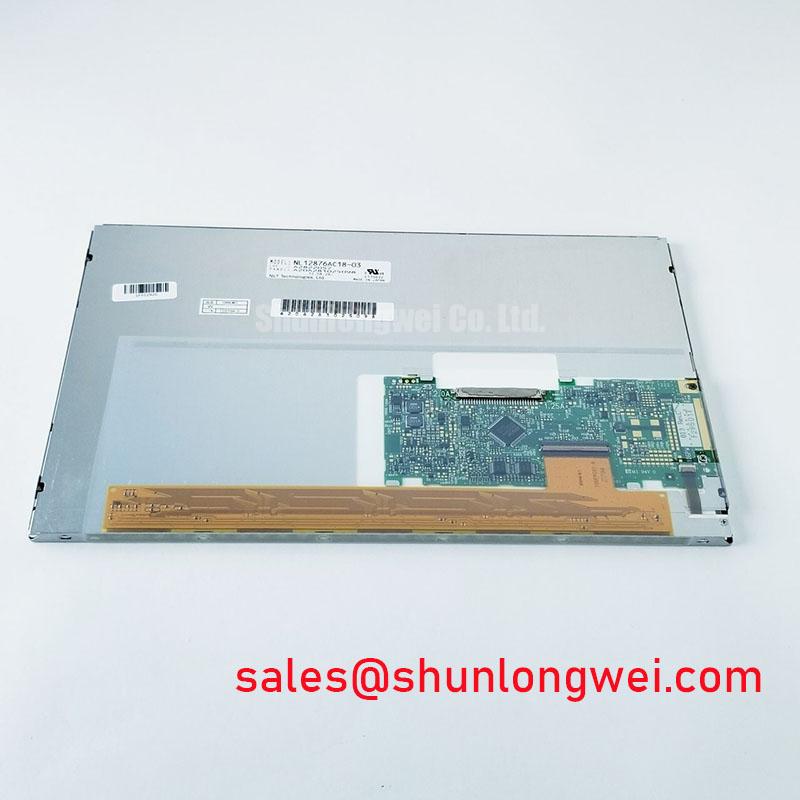
Backlight troubleshooting should begin by confirming what the original equipment documentation specifies for the installed display assembly. The official product record for NL12876AC18-03 identifies a TFT-LCD display module but does not state whether its illumination system uses CCFL or LED technology. It also does not provide lamp ignition voltage, LED-driver current, dimming method, PWM frequency, acoustic characteristics, backlight lifetime, insulation rating, or dielectric-test requirement. None of these values should be assumed during repair planning.
If the original service documentation identifies a high-voltage backlight circuit, treat it as a hazardous system assembly. Use approved lockout procedures, appropriate probes, and the equipment manufacturer’s test method. A secondary circuit can retain energy or produce elevated voltage under certain operating conditions. Testing must be performed by qualified personnel using equipment rated for the expected measurement environment. Do not conduct ad hoc insulation tests on the LCD module when the manufacturer’s permitted test conditions are unavailable.
If the original design identifies an LED backlight system, verify the driver output, enable control, dimming control, connector retention, and thermal contact according to the equipment documentation. Flicker can originate from a number of locations, including controller timing, dimming control, supply instability, cable disturbance, or display assembly behaviour. Compare the suspect unit against a known-good assembly where possible and assess the waveform with suitable instrumentation instead of relying solely on visual judgement.
Audible noise from a display area should be localized carefully. It may come from a power converter, transformer, inductor, cooling fan, loose panel hardware, or an adjacent cabinet device. Operate the system only within its approved service conditions while isolating the source. The panel itself must not be credited with a specific electromagnetic-compliance certification, insulation qualification, or service-life figure unless that claim appears in the applicable manufacturer documentation.
For preventive maintenance, keep the display enclosure clean and dry, ensure the sealing surfaces remain continuous, and confirm that air paths are not obstructed by dust accumulation or displaced cable bundles. When reassembling the HMI, verify that no harness, gasket, fastener, or bezel feature places concentrated force on the TFT-LCD module. These are general integration practices intended to support objective inspection and controlled system validation.