

Content last revised on September 10, 2026
Thermal Dissipation and Light Guide Plate Preservation
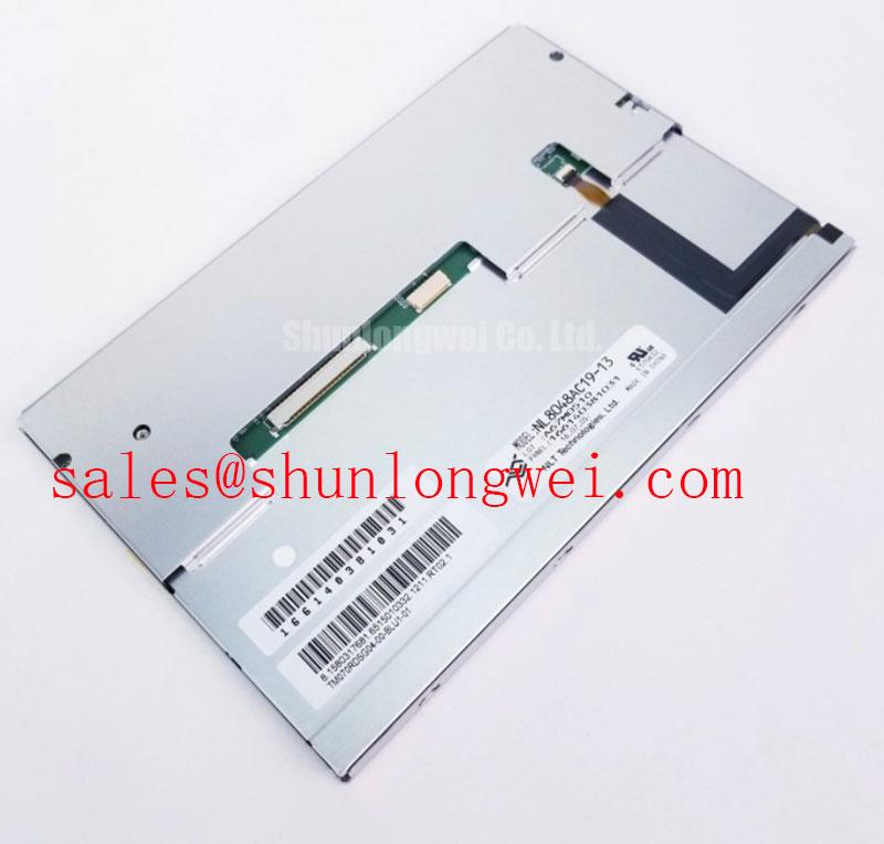
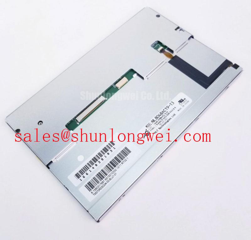
When an operator panel arrives with a dark edge, uneven brightness, or a shadow that changes after warmup, inspect the mechanical frame and backlight region before adjusting the host controller. A display module can show nonuniform illumination because of optical aging, driver instability, connector resistance, pressure from the bezel, or heat concentration at one edge. The available factory information for the NL8048AC19-13KD does not confirm a high luminance rating, an edge lit LED architecture, a PMMA light guide plate, an L70 value, or a B50 value. These features should not be treated as confirmed characteristics of this specific NEC model.
Design Consideration: If the replacement assembly uses an edge mounted light source, the equipment designer should provide a mechanically stable heat path around the active thermal zones without compressing the display glass or optical stack. An aluminum spreader rail may be evaluated where the enclosure transfers heat into the bezel, but the final arrangement must be validated by measuring the panel surface, frame, and driver temperatures during the actual duty cycle. The objective is to reduce localized hot spots while preserving optical uniformity; the correct rail size, contact method, and thermal interface remain system determined.
Do not infer a backlight fault from a dark image alone. A failed or disabled backlight can leave image data present, while a missing logic supply, absent enable signal, or defective timing path can produce a screen that appears equally inactive. Use a known good source or the original controller, then inspect the display under controlled ambient lighting. A flashlight test can help identify whether image content is present behind a dark screen, but it is a diagnostic indication rather than a model specific pass or fail threshold.
For installations in CNC operator panels or robot teach pendants, check the bezel opening, gasket compression, airflow path, and cable bend radius before final fastening. The supplied specification does not verify optical bonding, moisture sealing, dust protection, or a particular light guide material. If the panel is installed behind a sealed industrial window, the system integrator should verify condensation control and thermal performance at the enclosure level rather than attributing those capabilities to the LCD module itself.
Display Data Mapping Alignment and Even or Odd Channel Signal Integrity
Signal mapping must be confirmed before diagnosing a split image, incorrect colors, missing gray levels, or a display that shows alternating vertical bands. Display interfaces can use different data arrangements, and a cable that fits mechanically may still carry an incompatible mapping. The factory information supplied for the NL8048AC19-13KD does not identify the interface as LVDS or TTL, does not publish a connector pinout, and does not confirm VESA or JEIDA mapping. The original NEC documentation and controller schematic therefore take priority.
Design Consideration: Where the host electronics use a differential display link, route each pair as a controlled transmission path, maintain a continuous reference plane, and limit unnecessary stubs. A commonly used engineering target for differential display routing is 100 ohms, but that is a system design consideration and not an official electrical specification confirmed for this panel. The board designer should validate impedance, pair polarity, pair-to-pair timing, connector insertion loss, and common mode behavior against the selected transmitter, cable, and receiver.
Even and odd channel errors often require a comparison between the controller output and the panel input. Check whether the color order, red and blue placement, most significant bit position, and clock relationship match the source configuration. If the panel uses an LVDS receiver, the system integrator should verify the required logic supply voltage from the original panel documentation. Do not apply an assumed 3.3 V or 5 V rail simply because either value is common in industrial displays.
Power sequencing also belongs to the complete system validation. The host should confirm the order and timing of logic power, display enable, reset, video clock, and backlight control using the original documentation. The supplied data does not verify a specific rise time, enable delay, PWM frequency, dimming range, or clock jitter limit for the NL8048AC19-13KD. When the screen flickers or fails to start intermittently, capture the supply and control lines at the panel connector while comparing them with a known good unit.
For a neutral same class reference during a replacement review, engineers can compare the published information for NL10276BC16-06. That comparison does not establish interchangeability. Connector position, mounting dimensions, electrical mapping, backlight control, firmware timing, and optical characteristics must all match before a substitute is considered suitable.
Full Screen Primary Color AOI Screening for Stuck Sub Pixels and Background Uniformity
Run the display inspection with full screen red, green, blue, white, black, and neutral gray patterns after confirming that the controller is sending valid video. A practical service bench should record the result at startup and again after the panel reaches its normal operating condition. Look for stuck sub pixels, vertical or horizontal line defects, corner shading, mura, uneven white balance, and changes that follow cable movement. The available factory data does not provide a pixel defect class, luminance uniformity limit, contrast ratio, gamma table, or viewing-angle specification for this model, so the acceptance criteria must come from the original equipment manufacturer or the purchasing specification.
A 45 degree flashlight inspection can be used when the screen appears black. Illuminate the surface obliquely while observing whether faint menus, cursor movement, or test patterns remain visible. Image content visible under external light may direct attention toward the backlight circuit, while no visible content calls for checks of logic power, timing, interface activity, and controller status. This method cannot by itself distinguish an LED driver issue from a panel receiver or timing-controller failure.
The timing controller, gamma references, and gray-scale behavior should be assessed as a system. If mid-gray steps are crushed, tinted, or unstable, compare the video source, panel configuration, and reference rails with a known good assembly. The supplied factory context does not confirm internal gamma voltages, T-CON architecture, TTL or LVDS clock margins, or data hold times. Avoid probing exposed panel contacts unless the service procedure specifically permits it, since probe loading and electrostatic discharge can alter the evidence.
For automated optical inspection, use a repeatable camera position, stable ambient illumination, and consistent test patterns. Inspect the active area without pressing on the glass. A line defect that changes when the bezel is touched may involve mechanical stress or an interconnect condition, but the cause still requires confirmation through controlled comparison. AOI findings should be correlated with electrical measurements and visual inspection rather than assigned to one internal mechanism without evidence.
⚠️ Field Alert: Disconnect power and wait for the equipment service procedure to release stored energy before inserting or removing the display cable, because signal pins can be exposed to damaging transients during live connection.
Backlight Inverter and Ignition Debugging
Do not assume that the NL8048AC19-13KD uses CCFL tubes, LED backlighting, a dual channel inverter, or a particular ignition voltage. None of those backlight details are confirmed in the supplied factory specification context. A replacement decision should begin by identifying the original backlight connector, driver board, enable method, dimming method, and current or voltage requirements from the panel documentation.
If the original assembly is documented as CCFL based, ignition behavior should be assessed with equipment rated for the applicable high voltage and frequency. Inspect lamp connectors, insulation, transformer output, inverter protection behavior, and cable routing. A cold start that produces brief illumination followed by shutdown can involve lamp aging, open circuit detection, inverter protection, connector contamination, or an unsuitable control signal. The available data does not verify a 1500 to 1650 Vrms striking requirement, so that range must not be applied to this model without documentation.
If the documented assembly is LED based, evaluate the constant current driver, enable signal, PWM input, and thermal behavior under the actual brightness command. Do not substitute a presumed 1000 to 1 dimming range or a presumed PWM frequency for the original electrical limits. Audible noise can be associated with magnetics, switching control, mechanical resonance, or an unstable dimming interface; an oscilloscope and controlled brightness sweep can help isolate the behavior without treating one symptom as proof of a single cause.
When a CNC operator panel or robot teach pendant shows a backlight fault after replacement, compare the original and replacement connector functions point by point. Confirm whether brightness is controlled by analog level, PWM, serial command, or a dedicated enable line. The system integrator should verify the required supply voltage and backlight drive conditions from the original NEC documentation. A compatible mechanical size alone is not enough to establish electrical compatibility.
Reliability expectations should also remain evidence based. The supplied information does not publish a half-life, MTBF, field failure rate, or guaranteed operating-life figure for this model. Enclosure temperature, duty cycle, vibration, contamination, connector retention, and power quality all influence the completed HMI assembly. For broader guidance on integrating industrial displays in demanding enclosures, consult Industrial Display and HMI Solutions and validate the final assembly under the equipment manufacturer’s test conditions.