Content last revised on November 4, 2026
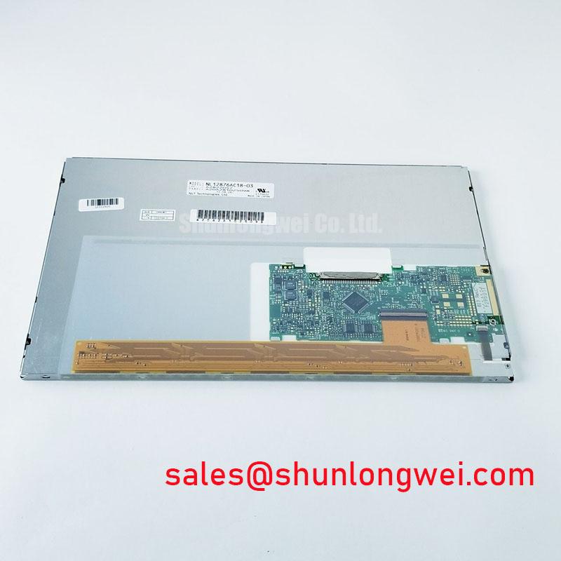
NL12876AC18-03BD Panel Identification and Initial Checks
- With the machine isolated, inspect the panel cable and connector seating before disturbing the display assembly.
- Compare the panel label and mechanical outline with the installed unit and the machine’s service documentation.
- Check the display supply and backlight driver at their designated test points, following the equipment maker’s isolation procedure.
- Record whether the fault is a blank screen, faint image, intermittent image, or image corruption before replacing parts.
NL12876AC18-03BD is identified as a NEC TFT-LCD active-matrix color display module in an industrial LCD/HMI panel category. The available product information identifies its model, manufacturer, and display type; it does not establish resolution, diagonal size, interface pinout, logic voltage, backlight type, brightness, or operating-temperature limits. Treat those as replacement-critical fields and match them against the original panel label and machine documentation before installation.
| Attribute | Product information |
|---|---|
| Model | NL12876AC18-03BD |
| Manufacturer | NEC |
| Product category | LCD panel for industrial display/HMI applications |
| Display construction | TFT-LCD active-matrix color display module |
| Resolution, interface, supply, backlight, dimensions | Consult the original panel documentation |
Backlight Fault Diagnosis and Driver Testing
The available product parameters do not identify this panel’s backlight technology or driver requirements. On a machine with a dark screen, first distinguish a completely inactive display from a faint image visible under oblique light. A faint image can direct attention toward the backlight path, while a fully blank screen also warrants checks of panel power, image data, and connector seating.
Inspect the machine’s backlight supply and return wiring against its service documentation. If the equipment uses a high-voltage lamp inverter, treat its output as a hazardous circuit and use appropriately rated test equipment and the prescribed discharge procedure; do not probe exposed secondary connections casually. If it uses another backlight arrangement, follow that driver’s own test method. The panel model alone does not establish an ignition voltage, dimming method, acoustic-noise limit, or lifetime rating.
Optical checks should be made with the panel installed in its intended enclosure and viewed under the actual shop lighting conditions. Contrast, glare, and readability depend on the complete optical stack, viewing angle, ambient illumination, and any cover window. Anti-glare or anti-reflection treatment and sunlight readability are not established specifications for this part. NEC’s display and technology information can provide manufacturer context, but it does not replace the panel-specific interface and optical documentation.
Interface Identification, Signal Timing and Cable Checks
Identify the connector and signaling standard from the original panel drawing before checking timing or wiring. The connector pin count is not established by the available product information for NL12876AC18-03BD. Do not assume LVDS, TTL, a particular data mapping, or a 3.3 V or 5.0 V supply from the model string.
For a no-image or split-image fault, compare the machine controller’s panel configuration with the panel documentation: interface type, lane assignment where applicable, pixel format, clock polarity, and timing parameters all need to agree. Check that the cable is fully seated and undamaged, then inspect the signal at the receiving end using probes appropriate to the confirmed interface and a known-good reference where available. A mismatch can produce unstable, displaced, or incomplete image content; the observed symptom alone does not identify which setting is wrong.
Keep any replacement cable routing and termination consistent with the specified interface and the equipment design. A nominal 100-ohm differential route is a common LVDS design consideration, not a confirmed specification for this model or its cable. The same discipline applies to clock skew and power sequencing: use the panel’s specified limits rather than importing generic timing values. LQ121S1LG45 may be useful as a comparison when evaluating another display, but its fit and electrical compatibility must be assessed independently.
Brightness Uniformity and Mechanical Checks
Assess brightness uniformity with the display warmed and operating in its normal enclosure, then compare the result with the equipment’s known-good condition. A dim edge, uneven field, or gradual brightness change can arise in the backlight, its driver, the optical assembly, or the supply path. The available product information for NL12876AC18-03BD does not specify LED construction, L70/B50 lifetime, or a constant-current driver, so those characteristics should not be assigned to the panel.
Inspect the rear mounting surfaces and enclosure for uneven pressure, debris, or a bent frame that could distort the display assembly. As a design consideration, thermal paths and local heat sources should be reviewed where brightness changes are concentrated near an edge. Do not add a heat spreader or alter clamping without checking mechanical clearances and the machine’s thermal design.
Where the display uses a separate controller board, inspect its grayscale and gamma configuration alongside the image source; an incorrect mapping can look like a brightness fault even when the backlight is steady. TCG121XGLPCPNN-AN70 is a separate display product reference. Its suitability as an alternative must be assessed independently from the respective electrical and mechanical documentation.
Signal Integrity and Intermittent Image Faults in Industrial Cabinets
When horizontal bands or intermittent pixels appear near a motor drive, compare the fault with machine operating states and inspect the display cable route, connector retention, and bonding points. Keep display wiring separated from noisy power conductors where the cabinet layout permits, and preserve the equipment’s intended grounding scheme. Shielding and ferrite components are system-level design choices, not confirmed features or required accessories for this panel.
If the interface is differential, capture the signal at the panel end with suitable probes and compare clock and data quality with a stable operating condition. Look for changes correlated with motor switching, cable movement, or connector pressure; avoid inferring a specific failure from a single waveform feature. The correct common-mode range, termination, and timing limits must come from the applicable interface and panel documents.
For a machine-tool operator terminal, verify that the replacement matches the existing outline, connector orientation, interface, and mounting arrangement before energizing it. Field Alert: Disconnect power before inserting or removing the panel cable to avoid stressing the interface during connection.
For broader system-level integration considerations, see Industrial Display & HMI Solutions. NEC is the identified manufacturer; industrial TFT display information offers general industry context, not specifications for this model.