Content last revised on September 10, 2026
NL12876BC26-21 NEC TFT LCD Display Module for Industrial HMI
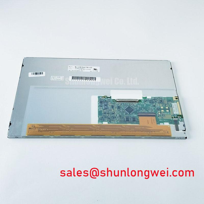
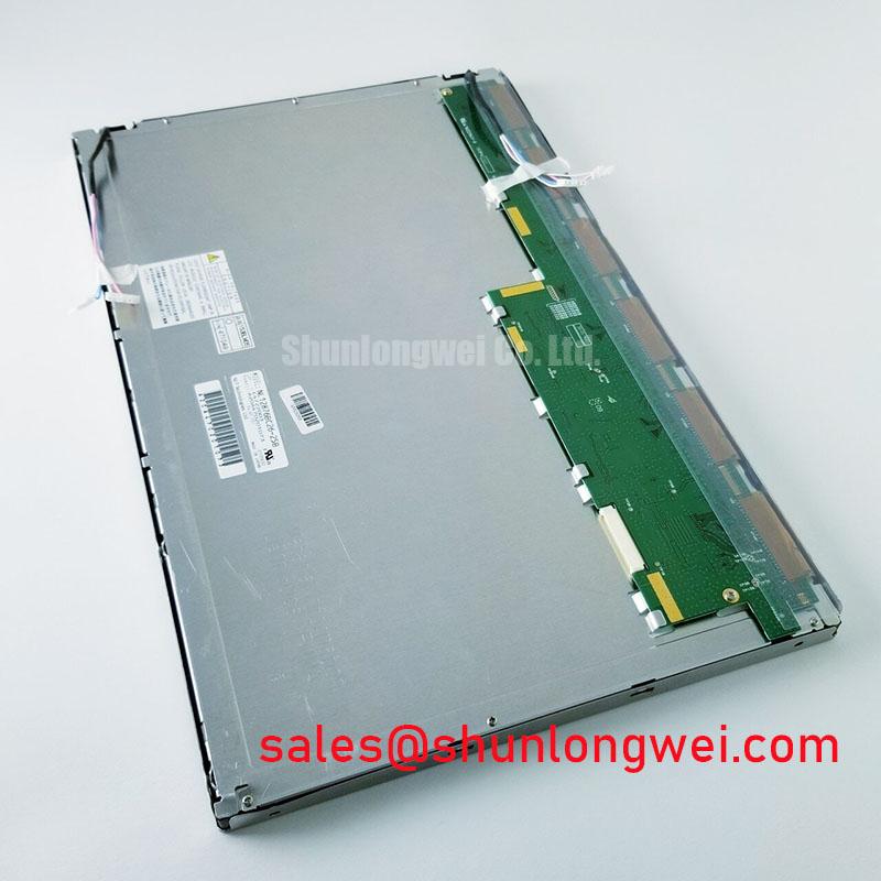
Begin a replacement check by comparing the installed panel label, connector position, mounting pattern, and cable orientation with the proposed NEC NL12876BC26-21 unit, then isolate power before disconnecting the display cable. The available factory information identifies this product as an Industrial Grade LCD/HMI Panel supplied as a TFT-LCD Display Module. Its specification status is listed as Official Factory Spec Verified.
This page is intended for maintenance engineers and procurement teams evaluating a display replacement for industrial control equipment. The supplied factory data does not confirm the panel diagonal, active matrix resolution, luminance, viewing technology, interface pinout, supply voltage, backlight architecture, connector series, or mechanical drawing. Those values should be taken from the original NEC documentation or the equipment manufacturer’s service documentation before electrical connection or enclosure modification.
Industrial EMI Noise Immunity, Chassis Shielding Continuity & Common-Mode Ferrite Chokes
For a high-voltage substation protection or SCADA dispatch console, the display should be evaluated as part of the complete signal and chassis system rather than as an isolated replacement. The NL12876BC26-21 product identity confirms the display module category, but it does not by itself define the host controller interface or guarantee system-level EMC performance. The system integrator should therefore compare the original cable assembly, connector keying, signal format, grounding arrangement, and cable route before selecting a replacement.
Where the host uses an LVDS connection, inspect the differential pairs from the controller board to the display connector for crushed insulation, contamination, unsupported cable sections, and contact fretting. A replacement cable with a different pair arrangement can create signal integrity problems even when the connector appears mechanically compatible. Confirm the original documentation for pair polarity, clock arrangement, data mapping, power pins, enable signals, and any display identification lines. Do not infer these functions from connector appearance alone.
A continuous chassis reference around the cable entry can reduce the coupling path for common-mode interference. This is a Design Consideration, not an NEC factory specification for this model. Engineers may assess shield termination, cabinet bonding, and the position of common-mode filtering where the display cable passes near switching power stages or motor-drive wiring. The filter selection remains system-dependent because excessive common-mode impedance can affect signal edges, while an unsuitable component can introduce resonance or create an unintended return path.
During commissioning, compare the suspect display with a known-good signal path using an oscilloscope or suitable protocol analysis equipment. Observe the pixel clock, differential amplitude, eye opening, and image stability while the surrounding equipment changes operating state. Horizontal bands, intermittent image loss, or isolated color disturbances may indicate a cable, grounding, timing, or controller issue rather than a defective LCD module. The correct diagnostic method is to test the complete path in a controlled sequence.
The linked NL8048AC19-13KD may be reviewed as a separate same-family display reference during sourcing research, but its electrical and mechanical compatibility with the NL12876BC26-21 must be established independently. Similar branding or a related product family does not establish interchangeability.
Dynamic Contrast Ratio Stabilization & Liquid Crystal Birefringence Temperature Tracking
The supplied factory record does not identify whether the NL12876BC26-21 uses TN, IPS, MVA, or another liquid-crystal viewing architecture. It also does not state a contrast ratio, viewing-angle specification, gamma table, response time, optical compensation method, or surface treatment. These values must not be substituted with typical figures from another panel family. For procurement approval, request the original optical specification and compare it with the display currently installed in the console.
In a protection or dispatch terminal, text readability is often more important than headline contrast measured under laboratory conditions. Inspect the replacement panel with the actual font size, alarm colors, mimic diagrams, and screen background used by the control application. Check the image from the operator’s normal position and from the side positions used during maintenance. Viewing-angle behavior, grayscale inversion, color shift, and reflected ambient light can change the usability of a console even when the image appears correct during a brief bench test.
Temperature should also be considered during evaluation. Liquid-crystal optical behavior can vary with temperature, but the magnitude and direction of that variation are panel-specific. Because the available information does not provide a temperature range or optical temperature curve for this model, the integrator should verify the original environmental specification and perform a warm-up assessment inside the intended enclosure. The test should include startup, steady operation, brightness changes, and the highest expected surrounding equipment temperature.
The controller board’s T-CON and gamma arrangement must remain compatible with the replacement panel. Confirm the timing parameters, frame format, grayscale control, power-on sequence, display enable behavior, and any required reset timing from the source documentation. A panel can remain unlit or display unstable imagery when its basic supply is present but its timing or control sequence is incorrect. This is a compatibility question, not evidence that the LCD glass itself has failed.
Backlight control also requires documentation review. The available factory data does not confirm whether this specific unit requires a CCFL inverter, an LED constant-current driver, an analog brightness input, a PWM input, or an integrated backlight circuit. The system integrator should verify the required supply voltage and backlight control method from the original panel documentation. If PWM control is used in the host system, engineers should evaluate flicker, visible stepping, acoustic behavior, and brightness linearity across the actual operating range instead of importing a generic frequency or duty-cycle prescription.
The separate NL128102BC28-04 can be examined as a related display solution when reviewing a broader sourcing plan. It should not be treated as a substitute for the NL12876BC26-21 without confirming the interface, optical, electrical, and mechanical requirements.
Thermal Expansion Clearance Sizing across Heavy Industrial Metal Enclosure Cutouts
Mechanical inspection should begin with the existing cutout and mounting arrangement. The NL12876BC26-21 is identified as a TFT-LCD Display Module, but the supplied factory parameters do not include its outer dimensions, active-area dimensions, bezel thickness, mounting-hole layout, fastener specification, or allowable compression. Measure the original assembly and obtain the applicable NEC mechanical drawing before machining a replacement aperture.
A metal enclosure can transmit vibration and thermal expansion directly into the display bezel. The installation should support the module without twisting the frame or placing concentrated load on the visible area. This is a Design Consideration; it is not a model-specific mounting instruction. Designers should verify the panel’s permitted mounting method, gasket arrangement, fastener pattern, and clearance requirements from the original mechanical documentation.
Do not use the visible glass edge as a reference for machining. Establish the datum from the enclosure drawing and then check the bezel overlap, cable bend path, connector access, and service clearance. The display must remain seated when the cabinet door is opened, when cable strain is applied during maintenance, and when the enclosure reaches its expected operating temperature. If a protective window is fitted, confirm that its spacing and optical finish do not introduce glare, Newton-ring effects, or localized pressure on the panel.
Fastener torque is also system-dependent. The supplied information does not specify an M3 torque limit for this model, so a generic value must not be presented as an NEC requirement. Use the original assembly instruction or the fastener and bracket manufacturer’s controlled work instruction. Tighten progressively in a cross pattern only when the approved mechanical procedure calls for it, and verify that the bezel remains flat after installation.
Thermal management should focus on the complete enclosure. Review heat sources behind the panel, airflow restrictions, converter placement, and the temperature of the cable and connector area. The factory data supplied here does not state backlight power, thermal resistance, maximum surface temperature, or expected service life. Field lifetime and failure-rate figures therefore cannot be assigned to this product without an authoritative test source. A practical acceptance test is to operate representative screens while recording the enclosure temperature and checking for image nonuniformity, brightness drift, or intermittent control behavior.
💡 Pro Tip: Keep the display signal cable separated from noisy power wiring where the cabinet layout permits, and verify the final image with the enclosure closed rather than relying only on an open-bench test.
Backlight Architecture and Insulation Testing
The supplied official product context does not state that the NL12876BC26-21 uses a CCFL backlight, an LED backlight, or an integrated high-voltage inverter. It also does not provide an ignition voltage, insulation rating, hipot requirement, PWM dimming range, MTBF, half-life value, or safety certification. The values sometimes associated with legacy display backlights must not be assigned to this model without a model-specific NEC document.
Before connecting a replacement to a substation console, identify the backlight architecture in the original assembly. Trace the cable to the display and determine whether the host contains a separate inverter, a constant-current driver, or another backlight supply arrangement. Check connector pin functions against the original drawing and inspect the insulation, spacing, strain relief, and enclosure barriers. A matching connector does not prove that the voltage, current, enable logic, or dimming control is compatible.
Any high-voltage backlight circuit must be tested under the equipment manufacturer’s approved safety procedure. Isolation testing, creepage and clearance review, protective-earth continuity, and discharge verification belong to the complete assembly and its applicable compliance process. A discrete display module cannot be described as independently compliant with an entire system EMC or safety standard. The responsible engineer should select the test method and limits from the relevant equipment specification and applicable standards.
For a console experiencing a dark screen, first separate the image-generation path from the illumination path. Confirm whether the controller is producing a valid image signal, whether the panel receives the documented supply, and whether the backlight enable command is present. Use non-invasive voltage and continuity checks appropriate to the circuit, then compare results with a known-good unit or the original service data. Avoid applying an unverified external supply or improvised inverter, since this can damage the module and create a hazardous condition.
Brightness control should be validated at the system level. If the original assembly uses PWM, confirm the input logic, polarity, permitted signal conditions, and response behavior from the panel documentation. If it uses an analog or dedicated driver interface, preserve that topology unless the manufacturer’s engineering documentation authorizes a change. Claims such as a particular dimming ratio, backlight half-life, or guaranteed operating hours require a source specific to the exact model and operating conditions.
For broader enclosure, cable, grounding, and display integration guidance, engineers may consult Industrial Display & HMI Solutions. When evaluating the NL12876BC26-21 for a high-voltage substation protection or SCADA dispatch console, final approval should be based on documented interface compatibility, measured mechanical fit, verified backlight requirements, and system-level functional testing.