

Content last revised on September 12, 2026
Initial Inspection of F-51136NCWHU-FW-AA
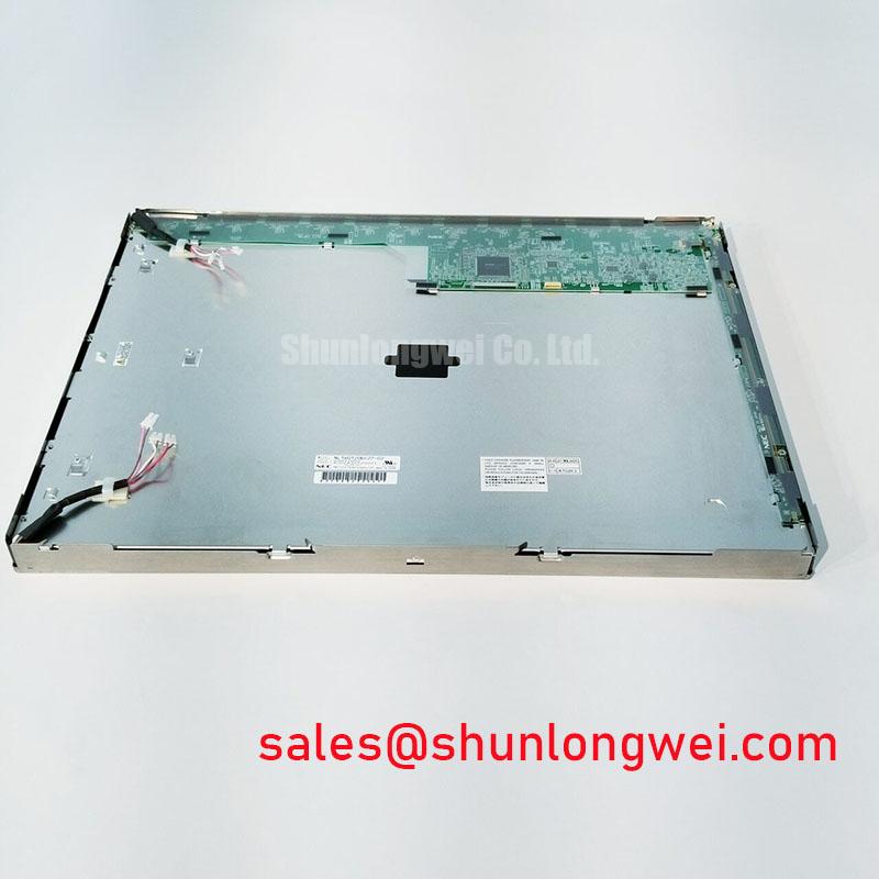
With the controller fully powered down, inspect the display connector, mating cable, panel edges, and front surface of F-51136NCWHU-FW-AA before attempting any powered test. This OPTREX unit is identified as an Industrial Grade LCD/HMI Panel in a TFT LCD Display Module format, with its specification status recorded as Official Factory Spec Verified. Confirm that the module part number matches the original service documentation and that the host equipment uses the same mechanical, signal, and backlight interface arrangement.
A controlled incoming inspection should begin with a clean, diffuse full screen image after the host system has completed its normal startup sequence. Check for persistent bright or dark pixel points, pressure marks, edge light nonuniformity, intermittent image loss during careful cable observation, and colour shifts that appear only at specific viewing positions. These observations help separate panel level concerns from issues originating in the host controller, cable assembly, power rails, or timing configuration.
| Model | F-51136NCWHU-FW-AA |
| Manufacturer | OPTREX |
| Product Category | Industrial Grade LCD/HMI Panel |
| Module Format | TFT LCD Display Module |
| Specification Status | Official Factory Spec Verified |
Backlight Driver Identification, Dimming Assessment, and Flicker Investigation
The available factory identification confirms the product category and module format, but does not establish the backlight technology, lamp count, LED string arrangement, input voltage, dimming method, brightness rating, or lifetime rating. The system integrator should verify the required backlight supply and control interface from the original panel documentation and from the connector pin assignment before connecting a bench supply or replacement controller.
This distinction matters during service work because a display can receive valid image data while remaining dark, visibly unstable, or unevenly illuminated because the backlight control path is incorrect. A host board can employ a dedicated enable line, an analogue brightness command, a pulse width control input, or a driver arrangement that is specific to the original equipment. Treating any of these as interchangeable without documentation can produce misleading test results or place stress on the display assembly.
For a controlled test, first observe whether the host equipment presents a stable image under normal operating conditions. Then compare brightness behaviour across the complete adjustment range available in the original human machine interface. If visual flicker becomes apparent during dimming, inspect the host brightness signal and driver output with suitable test equipment, comparing them against a known good channel where possible. Flicker may relate to the source control waveform, a driver supply disturbance, cable contact resistance, display settings, or interaction with ambient lighting; it should not be attributed to one cause without measurement.
Acoustic noise from a display area or nearby inverter board also requires careful isolation. It can originate from the panel backlight assembly, power magnetics, supporting capacitors, mechanical mounting, or the equipment enclosure. Disconnecting and reconnecting only with power removed, followed by controlled observation of the sound while the original system operates, provides more useful evidence than replacing parts based solely on audible symptoms.
For general industrial display context, the technical material in The Ultimate Guide to Industrial TFT LCD Technology can help technicians distinguish panel, backlight, interface, and enclosure level considerations. It should be used alongside the equipment manufacturer’s original documentation rather than as a substitute for the confirmed interface requirements of this specific OPTREX module.
💡 Bench Tip: Use ESD controlled handling and keep the display cable perfectly square to its connector before locking it, because a partially seated fine pitch connection can imitate a panel defect during a powered inspection.
TTL Digital RGB Bus Synchronization and Logic Power Rail Verification
The factory information supplied for F-51136NCWHU-FW-AA does not confirm the logic interface type, logic rail voltage, connector pinout, colour mapping, signal polarity, clock relationship, or timing requirements. These details must be verified from the original panel documentation before a replacement module is connected. It is not appropriate to assume a TTL, LVDS, JEIDA, VESA, or other interface format from the product category alone.
During a repair evaluation for a CNC operator panel or robot teach pendant, begin at the host cable and connector rather than at the displayed symptom. Look for latch damage, conductors pulled from the cable termination, uneven insertion depth, contamination, sharp bends close to the connector, and strain transmitted from a front enclosure. A display that shows unstable colour, repeating vertical structures, a partial image, or an intermittent blank field may be receiving compromised data, clock, or power signals. The panel itself should only be considered after the known good signal path has been checked.
Signal integrity is a Design Consideration for any high speed display connection. Differential or parallel signal traces, return paths, cable routing, shielding, ground references, and source timing can all influence the margin available to the receiving interface. Designers should preserve the original routing arrangement and verify waveform quality at the receiving end when the equipment is exposed to servo drives, switching power supplies, contactor activity, or other sources of industrial electrical noise.
The logic supply must also be evaluated as a system behaviour rather than a static reading. A rail can appear correct on a handheld meter while still dipping, rising in the wrong sequence, or carrying excessive switching disturbance during startup. Use an oscilloscope and the original startup conditions to assess the rail together with enable lines and display data activity. If image corruption occurs only during machine motion or when a robot controller changes operating state, correlate the event with power and signal captures before making a component level decision.
Where a replacement display is being evaluated, retain the original cable and controller board whenever possible. Introducing several new variables at once can hide the actual fault. If a substitute cable is unavoidable, ensure that its physical keying, conductor count, shielding arrangement, and endpoint pin assignment are confirmed against the original assembly. The connector position alone does not establish electrical compatibility.
Viewing Direction, Grayscale Behaviour, and Surface Reflection Assessment
The supplied factory information identifies an industrial TFT LCD module but does not confirm the liquid crystal mode, viewing direction, viewing angle, contrast ratio, surface treatment, optical bonding construction, or touch overlay arrangement. The system integrator should verify these properties from the original panel documentation and from the installed assembly before judging whether the screen is suitable for a particular viewing position.
A practical optical inspection uses consistent test imagery rather than a single desktop background. Display full white, full black, primary colour fields, neutral gray fields, fine text, and a gradual grayscale pattern. Observe the panel from the normal operator position and from the positions where an operator may stand while servicing the equipment. Look for contrast loss, tone reversal, colour shift, reflections that obscure text, or a brightness gradient that changes with viewing position.
In an industrial automation enclosure, perceived image quality is influenced by more than the LCD panel. The front window, touch sensor, adhesive layers, bezel geometry, contamination, and ambient illumination can alter contrast and glare. A display that appears acceptable on an open bench can behave differently behind a protective front assembly. When integrating or repairing a CNC operator panel or robot teach pendant, technicians should assess the complete optical stack in the intended enclosure condition.
Surface marks should be distinguished from image defects. A light scratch, cleaning residue, pressure impression, or uneven protective layer can become conspicuous on a white field while remaining difficult to see with dark content. Use a nonabrasive approved cleaning method and inspect the surface under angled illumination before classifying the condition. Avoid applying pressure directly to the active viewing area during testing, as temporary visual distortion can complicate the assessment.
Industry resources from Sharp Display Solutions provide useful general reference material on industrial display and optical integration topics. Such guidance is a Design Consideration only and does not define an official optical specification for F-51136NCWHU-FW-AA.
Thermal Observation of the Display Assembly During Continuous Operation
The confirmed factory data does not provide a thermal operating range, backlight lifetime value, internal optical stack description, heat spreading method, or continuous duty rating for F-51136NCWHU-FW-AA. Claims concerning diffuser material, prism sheet construction, LED life, optical yellowing, or long term brightness retention must therefore be avoided unless they are supported by the applicable OPTREX documentation for this exact model.
Thermal evaluation remains useful during equipment repair because excessive local heat can reveal an enclosure, power, controller, or mounting issue. Run the original equipment with representative screen content and normal enclosure covers installed. Observe whether image stability, brightness behaviour, or touch response changes after the system has reached its ordinary operating condition. Compare the display perimeter, rear mounting region, cable exit area, and nearby power electronics for localized heat using suitable noncontact or contact measurement methods.
Where a panel is installed adjacent to controller boards or power conversion hardware, airflow paths and metalwork contact should be reviewed as a Design Consideration. The objective is to avoid trapping heat near the display assembly and to prevent cable routing from placing mechanical stress on connectors as the equipment warms. The actual thermal result depends on enclosure design, duty cycle, ambient conditions, screen brightness setting, internal dissipation, and the installation arrangement selected by the equipment designer.
Full screen white, gray, and dark patterns are useful during extended observation because they can reveal different brightness behaviour and expose nonuniformity that is not apparent on moving graphics. If the image remains stable but brightness changes unexpectedly, verify host brightness commands, supply behaviour, and enclosure temperature before making a determination. If the image itself becomes unstable, inspect logic power, connector engagement, cable condition, and controller timing signals against a known good path.
For replacement assessment, preserve the original mounting arrangement and avoid forcing the TFT LCD module into a bezel that does not align with its attachment points. Mechanical loading at the display edges can affect appearance, connector reliability, and long term serviceability. Compatibility for CNC operator panels and robot teach pendants should be determined from the verified mechanical drawing, interface documentation, host electrical design, and controlled functional testing.