





Content last revised on September 12, 2026
Sharp LQ5AW136R Inspection and Application Considerations
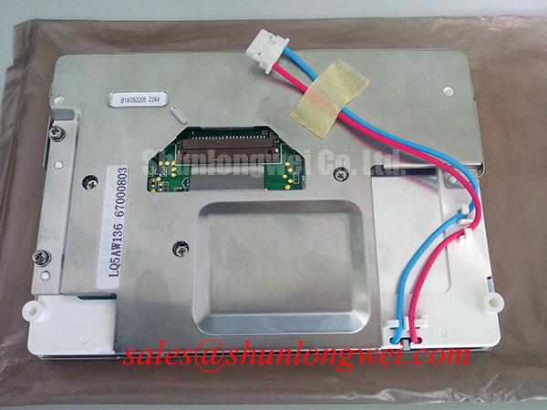
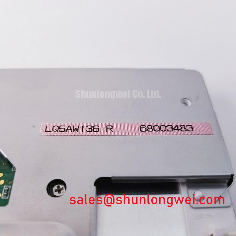
Begin incoming inspection by checking the Sharp LQ5AW136R TFT LCD Display Module for panel glass damage, frame distortion, connector contamination, and visible surface marks before applying power. The supplied factory data identifies this unit as an Industrial Grade LCD/HMI Panel with a TFT-LCD Display Module construction and an official factory specification status. Dimensions, resolution, interface pinout, supply voltage, backlight data, touch configuration, and operating temperature are not included in the available specification record, so the original panel documentation should remain the authority for final system approval.
| Model | LQ5AW136R |
| Manufacturer | Sharp |
| Product category | Industrial Grade LCD/HMI Panel |
| Package or housing | TFT-LCD Display Module |
| Specification status | Official Factory Specification Record |
For a replacement in a high-voltage substation protection or SCADA dispatch console, the display should be treated as part of a complete signal, power, mechanical, and optical chain. The LQ5AW136R model identity alone does not confirm interchangeability with another panel. The system integrator should verify the required supply voltage, display timing, connector arrangement, backlight drive method, mounting pattern, and touch interface from the original equipment documentation before installation.
Flashlight Dark-Shadow Optical Diagnostic to Isolate Logic and Backlight Fault Modes
Start the visual test with a clean, controlled image source rather than relying only on the equipment boot screen. Display a full-field white image, followed by red, green, blue, and black fields. Observe the panel from a normal viewing position, then inspect the surface obliquely with a flashlight held at approximately forty-five degrees. A dark shadow that reveals image content can indicate that image data is present while the backlight path is not producing normal illumination. This is a diagnostic observation, not a component-level failure verdict.
During the primary color sequence, look for fixed lines, repeated columns, localized color contamination, or areas that remain unchanged when the test image changes. These observations may involve the display signal path, connector seating, timing configuration, or panel drive circuitry. A dark region with visible image information should be evaluated separately from a region that contains no changing image data. Confirm the result by comparing the panel with a known-good signal source and by checking whether the host system reports a stable display link.
Ambient light can conceal low-contrast defects, while direct sunlight can create reflections that resemble uneven luminance. Record the inspection environment and viewing angle with every incoming inspection report. The available factory data does not specify a contrast ratio, ambient-light limit, anti-glare coating, or anti-reflective treatment for the LQ5AW136R. Those optical properties must therefore be verified against the original Sharp documentation or an approved equipment drawing rather than inferred from the model number.
Surface treatment also matters when the panel is installed behind a console window. A glossy surface may preserve apparent contrast in controlled indoor lighting but produce stronger reflections in a dispatch room with overhead luminaires. A matte or treated surface may reduce reflections while changing perceived sharpness. For a high-voltage substation SCADA console, the final assessment should be made through the actual enclosure window, with the intended screen graphics and normal operator viewing position.
💡 Bench Tip: Use ESD protection and confirm that every flexible cable is fully aligned before locking its connector; never force a cable into a partially offset socket.
Radiated Emissions Assessment and Backplate Grounding Around Industrial Drives
When the panel is evaluated near variable-frequency drives, contactors, or other high-current switching equipment, separate display faults from electromagnetic interference by repeating the image test with the surrounding power equipment in its normal operating state. A moving pattern of pixel jitter, intermittent horizontal noise, or unstable image content may be associated with cable routing, shield termination, grounding, signal integrity, power conversion, or the host controller. It should not be assigned to the LQ5AW136R alone without measurements at the display connector and source board.
Keep high-speed display cables physically separated from motor phase conductors and switching nodes wherever the equipment layout permits. If a shielded FFC or LVDS cable is used by the original design, reproduce the approved shield termination and chassis bonding arrangement rather than adding an arbitrary connection to the panel frame. Grounding points should follow the equipment manufacturer’s topology so that shield currents do not pass through sensitive signal returns.
Ferrite components and common-mode filtering can be useful design considerations when conducted or radiated interference is confirmed. Their selection depends on the actual cable, frequency range, source impedance, signal amplitude, and required data rate. A ferrite added without observing the signal eye or timing margin can change the link behavior rather than solve the disturbance. The system engineer should verify the display waveform with an oscilloscope at the receiving end and compare it with a known-good installation.
The LQ5AW136R is identified in the supplied data as an industrial LCD/HMI panel, but the record does not state independent CISPR Class A or Class B compliance. A display module cannot independently claim compliance for the completed SCADA console. EMC performance belongs to the assembled equipment, including the enclosure, cable harness, power supply, grounding, controller, and installation environment. Any radiated-emissions test should therefore be performed on the finished system under representative operating conditions.
For a broader review of panel interfaces, optical behavior, and selection factors, engineers can consult The Ultimate Guide to Industrial TFT LCD Technology. The article can support system-level screening, while the original Sharp documentation remains necessary for model-specific electrical limits.
Thermal Cycling Review of Panel Seals, Polarizer Surface, and Signal Connections
Temperature testing should begin with a visual and functional baseline at room conditions. Record the initial image uniformity, color fields, touch response if a touch layer is fitted in the equipment, and connector condition. Then expose the complete display assembly to the temperature profile specified by the equipment qualification plan. The available LQ5AW136R factory data does not provide a verified operating range, storage range, thermal-cycle profile, gray-to-gray response value, or sealant qualification, so no temperature limit should be assigned to this model from general industry practice.
After each temperature transition, allow the panel and its mounting hardware to stabilize before judging image quality. Inspect for edge discoloration, haze, bubbles, delamination, uneven illumination, frame stress, or a change in the apparent black level. These symptoms can have several possible sources, including enclosure pressure, cable contraction, power-supply drift, condensation, or panel aging. A controlled comparison against the pre-test image is more useful than identifying a single cause from appearance alone.
Cold operation can alter liquid-crystal response behavior and may produce visible motion blur or slower transitions, but the magnitude depends on the panel construction and drive settings. Do not apply a heater strip or modify the display timing unless the equipment documentation supports that method. If a heater is part of the existing design, verify its control logic, thermal sensor position, insulation, and effect on the panel frame. Local heating should be assessed for optical uniformity as well as startup performance.
Signal wiring deserves the same attention as the glass. Maintain the original cable bend direction and connector retention method. A cable that is electrically functional on the bench can become intermittent after thermal expansion, enclosure vibration, or repeated service access. When the interface uses a differential display link, the system designer should preserve the original controlled-impedance routing and pair balance. Exact impedance and skew limits must come from the controller and panel documentation, not from an assumed generic value.
For comparison work, the LMS700KF01-001 may be reviewed as a separate display option, but physical fit and electrical compatibility require a documented engineering comparison. A different panel size, connector, timing set, backlight requirement, or touch arrangement can prevent a direct replacement even when the application appears similar.
Suppressing Localized Thermal Gradients and Monitoring Optical Color Shift
Inspect luminance and color uniformity after the panel has reached its normal operating condition inside the intended enclosure. Use the same white, gray, and primary-color images used during incoming inspection. Pay particular attention to narrow edge zones, corners near brackets, and areas adjacent to power converters or warm structural members. A gradual yellow or warm shift can arise from several interacting factors, including local temperature, optical stack aging, backlight behavior, enclosure reflection, or camera exposure settings.
Do not attribute an observed color shift to a specific internal material or LED lifetime value unless that information is stated in the Sharp documentation. The supplied record does not specify an optical guide material, L70 or B50 life rating, LED current, luminance value, color temperature, or permitted thermal gradient. These parameters must be obtained from the original factory documentation before they are used in a maintenance plan or procurement specification.
A metal heat spreader or edge rail can be considered when thermal mapping shows a persistent hot area caused by nearby equipment. Its design must account for frame loading, insulation, clearance, service access, and the thermal path into the enclosure. The objective is to reduce unwanted local gradients without transferring heat into the display or obstructing the intended airflow. Final dimensions and materials should be determined from measured temperatures and the mechanical drawing.
If the original system uses PWM backlight control, evaluate flicker, audible artifacts, luminance linearity, and camera compatibility across the controller’s approved operating settings. The LQ5AW136R data supplied here does not confirm a PWM frequency, duty-cycle range, backlight current, or dimming interface. The integrator should verify these requirements from the original panel and controller documentation before changing the backlight driver.
For the surrounding display architecture, the LQ150X1LG11 can be examined as a separate Sharp display-related product reference. It should not be assumed to be a compatible backlight or companion module for the LQ5AW136R without confirmation of the system schematic, connector definition, optical requirements, and mechanical arrangement.
For purchasing and repair records, identify the panel as Sharp LQ5AW136R, retain the equipment part number alongside the display model, and record the verified interface and mounting information from the original machine documentation. This prevents a visually similar LCD/HMI panel from being released into a high-voltage protection or SCADA console without the required electrical and mechanical checks.