

Content last revised on October 6, 2026
High-Humidity Storage Margins and Delamination Prevention Protocols
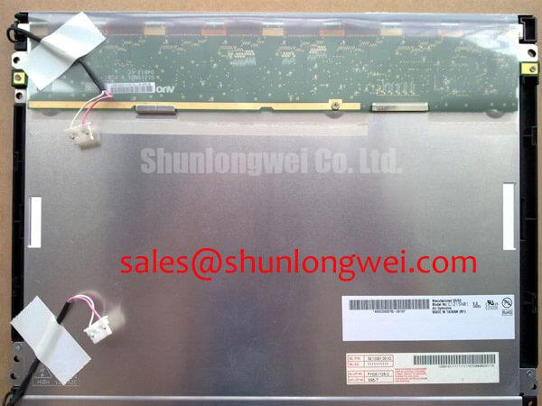
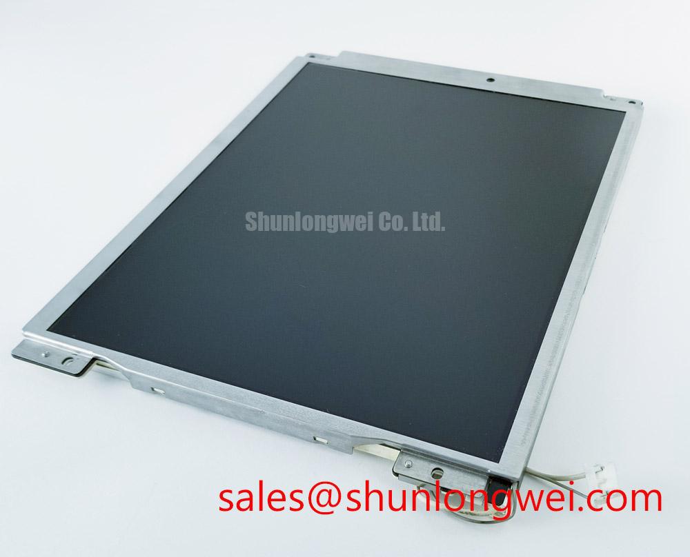
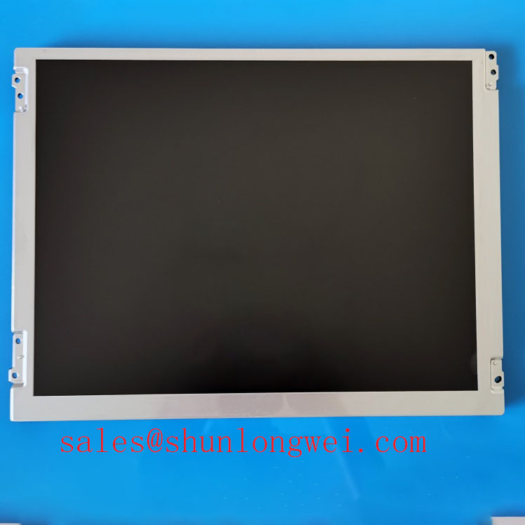
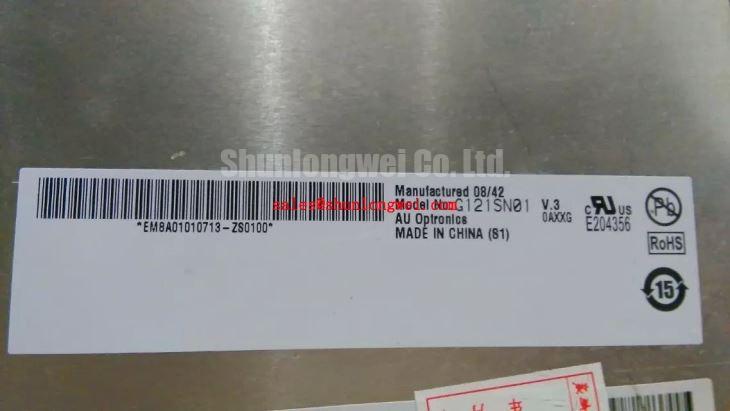
Inspect the G121SN01-V3 connector and display surface before applying power, then compare the unit’s label and mechanical fit with the panel removed from the equipment. This AUO TFT-LCD display module is identified in the supplied factory product information as an industrial LCD/HMI panel. Its supply voltage, interface pinout, backlight requirements, dimensions and environmental limits are not established by that information; obtain the original panel documentation before connecting it to an HMI controller.
Start a stored-panel inspection at the edges. Look for lifting layers, cloudy patches, staining near the perimeter and changes that remain visible with the panel switched off. Photograph any findings under consistent lighting before cleaning or energizing the assembly. Surface residue and an internal optical defect can look similar through a protective window, so inspect the window and the module separately wherever the equipment permits.
Design Consideration: Moisture trapped inside an operator-station enclosure can affect connectors and optical surfaces even when the display itself has not been shown to exceed a specified humidity limit. Check the enclosure gasket, cable entries and any signs of condensation before attributing an edge defect to the G121SN01-V3. Do not treat an enclosure’s environmental rating as a rating for the bare display module. The allowable storage humidity and temperature must come from the applicable AUO documentation for this revision.
After a cold start, moving graphics may appear slower as liquid-crystal response changes with temperature. That observation alone does not establish a defective panel. Compare the image after the equipment has stabilized, while recording the ambient condition and the controller output. If an installation uses a heater or a dimming circuit, verify its control against the host equipment documentation rather than assigning a frequency, duty cycle or temperature threshold to this module without a confirmed specification.
Power sequencing deserves the same care as environmental inspection. If a unit briefly shows a white screen at startup or retains an image during shutdown, capture the panel supply, video activity and backlight control at the connector during both transitions. The controller’s sequence determines whether valid image data is present when the display becomes visible. Field Alert: Disconnect equipment power before reseating the display cable. Any sequence correction should be validated against the original panel timing requirements, not inferred from the appearance of the screen alone.
Polarizer Durability and Optical Inspection under Industrial Lighting
Examine the unpowered panel first with reflected light, changing the viewing angle to separate marks on the front surface from marks beneath it. Then display a uniform image and repeat the inspection from the normal operator position. A bright workshop lamp can hide low-contrast defects while making scratches and glare prominent; keep the lighting arrangement consistent when comparing the installed panel with a bench unit.
The supplied identification does not establish the G121SN01-V3 liquid-crystal mode, viewing angles, surface treatment or optical-bonding construction. Do not assume TN grayscale inversion, IPS or MVA viewing behavior, or a particular anti-glare finish from the product category alone. For a cabinet mounted above or beside eye level, test the actual viewing position with the HMI’s normal colors and alarm screens. If a protective cover lens is present, inspect it independently before deciding whether a contrast or reflection complaint belongs to the display.
Design Consideration: A persistent control-room graphic can leave a temporary visible trace on some LCD installations. If an image remains after a screen change, compare its appearance after normal operation with a varied test image and check whether the controller is still presenting the old graphic. Avoid declaring permanent panel damage from a single photograph. The host application can be reviewed for screen changes or display-off behavior, but those measures must be assessed against its operating requirements.
For a dim screen, measure the relevant supply and backlight-control signals using the confirmed connector assignment. Also check the brightness setting and any external driver used by the equipment. A low-brightness complaint cannot establish a backlight lifetime, and no operating-hour or brightness-decay figure should be assigned to this module without its applicable specification and test conditions. If the assembly includes optical bonding or a sealed cover, verify that construction from its documentation; neither dust resistance nor moisture tightness follows from the LCD model name.
Industrial EMI Noise Immunity, Chassis Shielding Continuity and Common-Mode Ferrite Chokes
When horizontal bands or unstable pixels appear near running machinery, record whether the pattern changes with motor-drive operation, cable movement or enclosure-door position. Repeat the observation with a known-good video source where the equipment allows it. This separates a signal-path investigation from an optical defect investigation without assuming that electrical interference is the cause.
Trace the installed cable from controller to panel and compare its routing, shield terminations and connector seating with the equipment drawing. The supplied product information does not confirm an LVDS interface or a particular cable construction for G121SN01-V3. Identify the interface and pinout in the original panel documentation before probing signal contacts or specifying a replacement harness. If a common-mode choke or ferrite is already part of the host design, inspect its installation; adding one is a system-level decision that requires signal-integrity testing.
Design Consideration: Shield continuity and cable separation can reduce coupling in a noisy cabinet, but a display module by itself does not establish EMC compliance for the operator station. Verify any cable-routing change with the complete equipment operating in the conditions that produced the symptom. A hazardous-area petrochemical operator station is a possible compatibility evaluation case, not an application approval for this panel. The equipment designer must confirm enclosure suitability, interface compatibility and the applicable system requirements.
Cold-temperature motion lag can also make a changing image seem unstable. Before changing shielding hardware, compare stationary graphics with moving graphics and note whether the symptom follows ambient temperature or nearby equipment activity. For broader guidance on separating panel characteristics from enclosure and interface choices, consult The Ultimate Guide to Industrial TFT LCD Technology; the permissible limits for this model still require its own documentation.
Flashlight Dark-Shadow Optical Diagnostic to Isolate Logic and Backlight Faults
With the HMI powered and a known image commanded, direct a flashlight obliquely across a dark screen. A faint image suggests that image generation deserves separate consideration from illumination, but it does not prove a backlight fault. Confirm what the controller is sending, then check the panel supply and the installed backlight circuit using the correct documentation and safe access points. If no faint image is visible, continue checking power, video and connectors rather than assigning the failure to one part.
For a repeatable bench comparison, command uniform red, green and blue screens in turn through a compatible, documented controller. Note whether a line defect stays in the same position, whether it changes when the cable is gently secured, and whether it also appears on the controller’s output. Do not infer an internal driver fracture from a line pattern alone. Preserve the panel’s installed cable orientation and avoid pressure on the display surface while testing.
If the image appears normally but brightness is intermittent, inspect the equipment’s brightness command, backlight supply path and connector contact condition. If a white screen follows startup, capture the order of supply and image signals; if a residual image appears at shutdown, capture the shutdown order as well. Compare both records with the specified timing before changing the controller. The system integrator should verify the required supply voltage and interface from the original panel documentation.
For a repair material review, G104VN01 V1 can be recorded as another AUO panel to evaluate, not a confirmed drop-in replacement. Compare its active area, outline, mounting, connector, electrical interface, timing and optical characteristics against the G121SN01-V3 and the host equipment before any substitution decision.