

Content last revised on October 25, 2026
CCFL High-Voltage Resonant Inverter Striking Voltage & Ignition Debugging
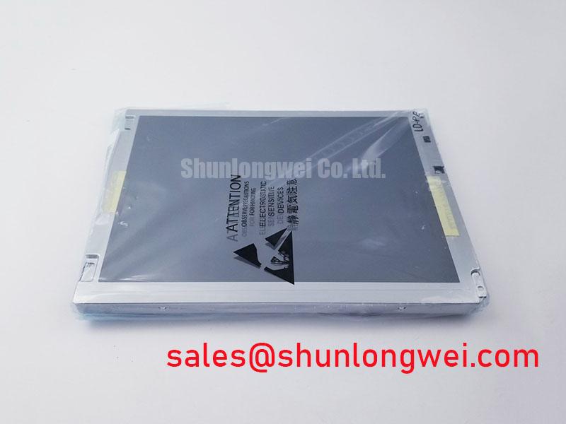
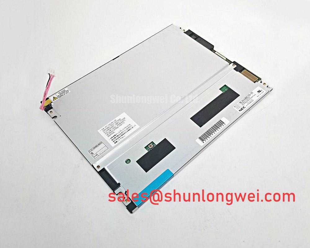
When a replacement panel shows a dark screen after installation, I first isolate the display module from the host controller and check whether the backlight architecture, inverter interface, and supply sequence match the original equipment. The NEC NL6448BC33-49 is a TFT-LCD active matrix color display module. The system integrator should verify the original panel’s backlight configuration and documentation before applying any high-voltage ignition procedure.
For equipment using a dual-channel CCFL inverter, cold-start behavior can be influenced by lamp condition, resonant transformer loading, cable routing, and the inverter’s protection logic. A high-voltage probe may be used by qualified personnel to compare ignition behavior with a known-good display assembly, but the probe must be suitable for the inverter output and connected only under an approved service procedure. A failure to strike can also result from an open lamp circuit, connector seating, inverter shutdown, or an incorrect enable signal, so the fault should not be assigned to the LCD panel without checking the complete backlight path.
If the replacement assembly includes an LED backlight conversion, its constant-current LED driver requires a different diagnostic approach. The technician should inspect the driver enable line, current feedback response, open-load protection, short-load protection, and brightness-control signal. PWM dimming behavior should be evaluated at the complete display assembly rather than inferred from the panel model number. Audible noise may originate from the inverter, a mechanically resonant enclosure, or an unsuitable dimming control path. A controlled sweep of brightness command and a comparison against the original assembly can help separate optical flicker from acoustic resonance.
Low-temperature operation can extend liquid-crystal response time and make gray-to-gray transitions appear slower. This is a system-level behavior affected by the panel, enclosure temperature, drive timing, and any approved thermal management hardware. For an AGV or forklift telematics display, the integrator should verify cold-start image formation, character readability, and backlight recovery after the vehicle has remained idle in a cold area. Published industrial display guidance from industrial TFT display solutions can provide useful context for evaluating optical and environmental requirements, but it does not replace the panel’s own documentation.
Industrial Bezel Mechanical Envelope Tolerances & Mounting Screw Torque Optimization
Mechanical installation should begin with a dimensional comparison between the removed panel, the replacement bezel opening, the mounting points, and the cable exit direction. For the NEC NL6448BC33-49, the enclosure designer should obtain the original mechanical drawing before machining a new bezel or selecting fasteners.
Uneven bezel pressure can create localized optical non-uniformity, edge brightening, dark-field mura, or visible color changes when the chassis is tightened. These effects may vary with temperature as the enclosure and panel expand at different rates. A practical incoming inspection uses a flat, clean support surface, a uniform test image, and photographs taken before and after the panel is secured. If the image changes after fastening, release the enclosure load and inspect the mounting interface rather than increasing screw force.
Cross-pattern fastening is a useful Design Consideration for distributing enclosure pressure, while the actual torque must be determined by the chassis material, fastener size, threaded insert strength, and the panel manufacturer’s mechanical documentation. Clearance around the active viewing area, cable bend radius, and access for service locking mechanisms should also be confirmed before production release.
Brightness control deserves a similar system-level check. If the backlight uses PWM, the controller should be evaluated for visible flicker, acoustic interaction, and duty-cycle tracking across the intended brightness range. The PWM frequency and duty-cycle limits should follow the backlight driver’s documentation. An AGV or forklift display enclosure should also be checked for vibration transfer, glare from warehouse lighting, and readability through the protective window.
Display Interface Timing, Pixel Clock & Signal Integrity
Before applying power, compare the replacement cable, connector keying, pin count, signal direction, and panel controller interface with the original assembly. Confirm the NL6448BC33-49 interface from its original documentation; a 20-pin or 30-pin LVDS connection must not be assumed. A connector that fits mechanically can still carry a different power arrangement, data mapping, or backlight control signal.
Use the original display documentation to confirm logic supply voltage, power sequencing, pixel clock requirements, and signal mapping. If an external LVDS receiver or adapter is used, also confirm its JEIDA or VESA mapping where applicable. The frequently encountered values of 3.3 V or 5.0 V are not interchangeable assumptions for this model. Observe the supply rise and display-control timing with an oscilloscope at the panel connector, using the original known-good unit as the comparison reference. Abnormal screen division, missing color groups, unstable synchronization, or a blank image may indicate timing, mapping, signal integrity, or power-sequencing problems.
For any LVDS link used upstream of a panel adapter, maintain a controlled and continuous reference plane, keep paired conductors together, and avoid unnecessary stubs near the connector. A nominal 100-ohm differential target is a common LVDS Design Consideration, but the board stack-up and cable construction determine the actual impedance. Skew compensation should be based on measured waveform alignment and the receiver’s timing window, not on a generic cable length rule. At the panel interface, follow the signal requirements documented for the panel itself.
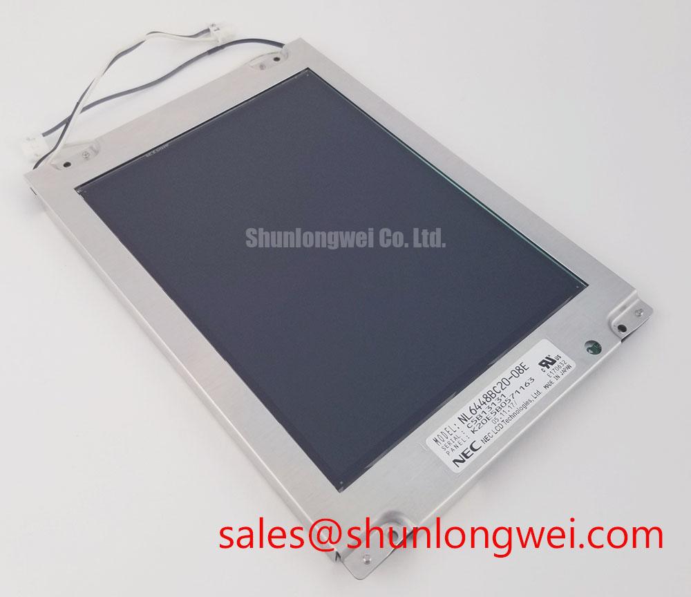
Cold-temperature testing should include the entire image path. Slower liquid-crystal transitions can be mistaken for pixel-clock instability when moving text or rapidly changing graphics are used as the test pattern. Static color fields, checkerboard images, grayscale ramps, and scrolling characters provide different evidence. When integrating the panel into a service replacement assembly, designers can compare the interface requirements with those of the NL6448BC20-08E as a separate display evaluation, without assuming mechanical, electrical, or timing compatibility.
Suppressing Pixel Jitter & Horizontal White Lines Induced by Adjacent 400V Motor Drives
When horizontal bands or pixel jitter appear near a variable-frequency motor drive, first separate the display signal cable from motor conductors, braking wiring, and switching nodes while preserving the original grounding arrangement. The NL6448BC33-49 should be tested with the complete host system because interference can enter through the display signal cable, logic supply, chassis reference, or backlight wiring.
A shielded display cable assembly may reduce radiated and common-mode coupling when its shield termination is compatible with the host enclosure. Shielding should not be added casually at both ends without checking the system grounding topology, as an unintended current path can worsen noise. Common-mode ferrite components are a Design Consideration for suppressing conducted interference, but their impedance profile, placement, current rating, and effect on signal edges require measurement on the actual cable assembly.
Use an oscilloscope to compare the display signal waveforms, ground-reference disturbances, and panel supply ripple with the motor drive disabled and enabled. Where an LVDS link is present, also examine differential pair behavior and common-mode movement. Correlating the disturbance with drive switching frequency can help distinguish conducted coupling from mechanical vibration or an unstable backlight controller. The display should also be checked with a static test pattern and a moving test pattern, since optical flicker and data corruption do not always appear in the same image conditions.
Backlight aging must be assessed from measured luminance rather than a generic operating-hour claim. Any half-brightness lifetime used for this NEC module should come from its documentation, including the stated operating conditions. For field replacement planning, record initial luminance, operating temperature, brightness command, and driver condition so future readings remain comparable.
💡 Bench Tip: Disconnect power before inserting or removing the display cable, use ESD protection, and confirm that the connector is fully aligned before locking the cable.
For enclosure, grounding, optical, and service-integration references, the Industrial Display & HMI Solutions engineering resource can be used alongside the original NEC documentation. General corporate information is available through NEC.