Content last revised on September 14, 2026
DMF50081NF-FW Inspection and Compatibility Review
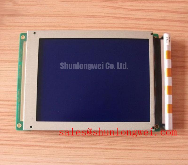
Begin the incoming inspection by confirming the DMF50081NF-FW identification marking, checking the TFT-LCD module housing for impact or compression marks, and comparing the original equipment documentation before applying power. The available factory context identifies this unit as a Kyocera / OPTREX Industrial Grade LCD/HMI Panel with a TFT-LCD Display Module package. The supplied official specification set does not state the panel resolution, active area, interface type, supply voltage, backlight architecture, luminance, viewing angle, operating temperature, or response time, so those values must be verified from the original panel documentation or equipment service manual before replacement.
| Parameter | DMF50081NF-FW Information | Classification |
|---|---|---|
| Model | DMF50081NF-FW | Official factory identification |
| Manufacturer | Kyocera / OPTREX | Official manufacturer context supplied |
| Product category | Industrial Grade LCD/HMI Panel | Official product category |
| Package or housing | TFT-LCD Display Module | Official structural description |
| Specification status | Official Factory Spec Verified | Supplied product record |
| Resolution, dimensions, interface, and electrical ratings | Verify against the original panel documentation | Not stated in the supplied factory parameter set |
For a hazardous petrochemical Zone-2 explosion-proof operator station, the display module should be assessed as one part of the complete enclosure and control assembly. The display itself must not be treated as independently certified for hazardous-area operation, EMC compliance, ingress protection, or explosion protection unless the applicable assembly documentation explicitly confirms those approvals. Designers should verify the complete station’s certification boundary, window construction, sealing method, cable routing, temperature limits, and maintenance procedure before approving this panel for field service.
Backlight Driving, PWM Dimming, and Flicker Suppression Considerations
The supplied official data for the DMF50081NF-FW does not confirm a WLED backlight, a CCFL backlight, a constant-current input, a PWM dimming ratio, or a specified PWM frequency. The system integrator should verify the required backlight technology and driver interface from the original panel documentation rather than assuming that an LED driver can replace the existing circuit. This check is important because a display module may require a dedicated backlight supply and control arrangement that is not interchangeable with a generic monitor power board.
If the original assembly uses a constant-current LED driver, the practical evaluation should begin with the driver’s output regulation, enable behavior, dimming input, and fault response. A current probe or carefully selected measurement point can help compare startup current, steady-state current, and brightness transitions against a known-good assembly. The measurement equipment and probe arrangement should be selected so that the display cable and backlight wiring are not mechanically stressed during testing.
A requested 1000:1 PWM dimming figure must be treated as an application target, not as a confirmed DMF50081NF-FW specification. The same applies to a proposed 200 Hz to 1 kHz control range. These values can be used only as a Design Consideration when the driver documentation supports them. The integrator should confirm that the selected PWM frequency avoids visible modulation, audible interaction with mechanical parts, and unwanted interference with the HMI controller. Brightness linearity should be checked across the intended duty range using the actual display, driver, camera exposure conditions, and ambient lighting.
When a backlight fault is suspected, separate the display signal path from the illumination path during diagnosis. A dark image with a valid video signal does not by itself identify the failed element. Check the driver enable state, current regulation, connector contact, and backlight output behavior while comparing the results with the original panel service data. The product record supplied for this model does not provide a guaranteed half-life, MTBF, or 50,000-hour backlight rating, so no service-life conclusion should be assigned without a manufacturer source.
LED Thermal Dissipation and Light Guide Plate Preservation
The DMF50081NF-FW record identifies a TFT-LCD display module but does not confirm edge-lit construction, a PMMA light guide plate, high-nits performance, aluminum rail geometry, or an L70/B50 rating. These internal or optical construction details should be verified from the approved technical drawing or original assembly documentation. Avoid adding a heat spreader, adhesive, spacer, or clamp based only on the appearance of a replacement module, because a change in mechanical pressure can affect optical uniformity and may transfer stress into the display assembly.
Thermal evaluation should focus on the complete installed stack. Inspect the rear clearance, ventilation path, bracket contact, cable bend radius, and any gasket that could block heat release. Measure temperature at repeatable external locations during representative image content and brightness settings, then compare the behavior with the original unit. The purpose of this test is to identify localized heating or enclosure-related heat accumulation; it does not establish the semiconductor junction temperature or an LED lifetime prediction.
For narrow edge-lighting arrangements, a Design Consideration is to distribute heat into the approved chassis path rather than creating a rigid point contact at one edge. The final mechanical solution remains system-determined and should be validated for flatness, optical uniformity, vibration, and thermal expansion. If the equipment manufacturer specifies a light guide, reflector, diffuser, or bezel arrangement, retain that geometry during service evaluation. The supplied factory information does not authorize a particular optical material or rail design for this model.
Backlight aging curves should be requested when brightness retention is a procurement requirement. A statement such as 50,000 hours to 50 percent brightness would require a clearly identified manufacturer test condition, current level, ambient temperature, duty profile, and applicable definition of failure. Without that source, the correct engineering action is to record initial brightness under a repeatable setup and define a field inspection method for gradual uniformity loss, edge discoloration, or localized brightness change.
Current measurement can be performed with an instrument suitable for the driver waveform. The Rogowski coil principle for fast transient current sensing provides useful background for non-intrusive transient measurement, while the ADI current sense amplifier resource can help engineers compare sensing approaches. These references describe measurement principles and are not specifications for the DMF50081NF-FW.
Incoming Benchtop Inspection of Display Interconnects
Incoming inspection should use a controlled visual and electrical sequence. First, display a full red, green, blue, white, and black image pattern from a known-good controller. Look for fixed lines, missing columns, nonuniform regions, and changes that follow cable movement. Second, inspect the bezel and glass edge under angled light for pressure marks, contamination, or mechanical distortion. Third, compare the panel with the original unit using the same signal source and viewing conditions. This sequence can narrow the fault area without assigning a single cause from one symptom.
A 45-degree flashlight inspection may reveal shadows, edge leakage, surface contamination, or areas where the illumination path is not uniform. It cannot by itself prove a COG or TAB bond failure. If a line defect remains fixed while the video timing and cable seating are confirmed, the engineer should compare the signal path with a known-good panel and use appropriate waveform measurements. Changes caused by connector movement, chassis pressure, or temperature should be documented separately because they may point to an interface or mechanical issue rather than a confirmed internal bond defect.
The supplied factory parameter set does not confirm the use of COG, TAB, or anisotropic conductive film in this exact module. Those construction features should therefore be treated as unverified until supported by manufacturer documentation. Service personnel should avoid pressing the glass edge or bonded region during diagnosis. Mechanical force can change the symptom and make later assessment less reliable.
T-CON timing, grayscale voltage generation, and gamma correction are also not specified in the supplied data. When a replacement panel shows incorrect gray transitions, color imbalance, or intermittent image retention, verify the controller compatibility, pixel clock, timing parameters, power sequence, and gamma configuration against the original system. Do not infer a particular gamma voltage range or T-CON architecture from the model number alone.
Wide-viewing-angle behavior should be evaluated with the actual front window, bezel, optical stack, and intended viewing direction. The available record does not identify IPS, MVA, or another LCD mode, nor does it specify viewing-angle compensation data. A Design Consideration is to compare grayscale and color shift at the operator’s normal sight lines rather than relying only on a central-axis image check. Any compensation must be implemented through the approved display controller or optical design and verified by the system engineer.
⚠️ Maintenance Note: Disconnect power before reseating the display cable, and inspect the cooling path and sealing gasket during every scheduled panel service.
Humidity and Temperature Storage Evaluation
The DMF50081NF-FW factory information supplied here does not publish a humidity storage rating, a 60°C and 90% RH qualification, a thermal cycling range, a perimeter sealant specification, or a delamination limit. Those environmental values must not be presented as guaranteed operating or storage capabilities. If a repair program uses elevated humidity and temperature as a screening condition, it should be defined by the equipment owner’s qualification plan and applied only with documented acceptance criteria.
Before installation, allow a cold module to reach the controlled service environment gradually. Inspect the glass, bezel, connector, gasket contact surface, and protective window for condensation or trapped moisture. In a sealed operator station, the enclosure pressure cycle, desiccant condition, cable gland arrangement, and temperature transitions can influence condensation risk. The display module alone cannot establish the environmental performance of the complete station.
Low-temperature operation can change liquid-crystal viscosity and increase perceived gray-to-gray response lag. The supplied record does not specify a low-temperature response curve or a heater requirement for this model. If the application includes sub-zero exposure, the integrator should verify image response, startup behavior, contrast, and condensation control at the actual enclosure conditions. Any heater strip, thermostat, or warm-up delay must be selected and validated by the system designer rather than assumed from the panel model.
For storage screening, record the pre-test visual condition, connector condition, image uniformity, and backlight behavior. After conditioning, repeat the same checks and look for haze, bubbles, edge separation, new nonuniformity, or changes in connector operation. A visible change does not identify one definite failure mechanism; it should be correlated with moisture history, mechanical mounting stress, temperature transition, and controller behavior.
Uniform mounting pressure is especially important for industrial HMI replacement work. The bezel should support the panel as specified by the original equipment design, while fasteners and brackets should be tightened evenly without forcing the glass or frame into a distorted position. Gasket compression should provide the intended environmental interface without blocking ventilation or creating a concentrated load. Engineers evaluating this module for a Zone-2 operator station should review the complete Industrial Display & HMI Solutions engineering context, then verify enclosure sealing, optical window compatibility, power sequencing, interface timing, and hazardous-area certification at system level.
Before approving the DMF50081NF-FW for field replacement, confirm the original module’s electrical interface, dimensions, mounting pattern, backlight requirements, controller timing, environmental limits, and complete equipment certification documentation. The verified product identity and package description support initial sourcing and compatibility review, while the unreported parameters remain approval items for the equipment manufacturer or system integrator.