Content last revised on October 26, 2026
CCFL Backlight Operation and Illumination Troubleshooting
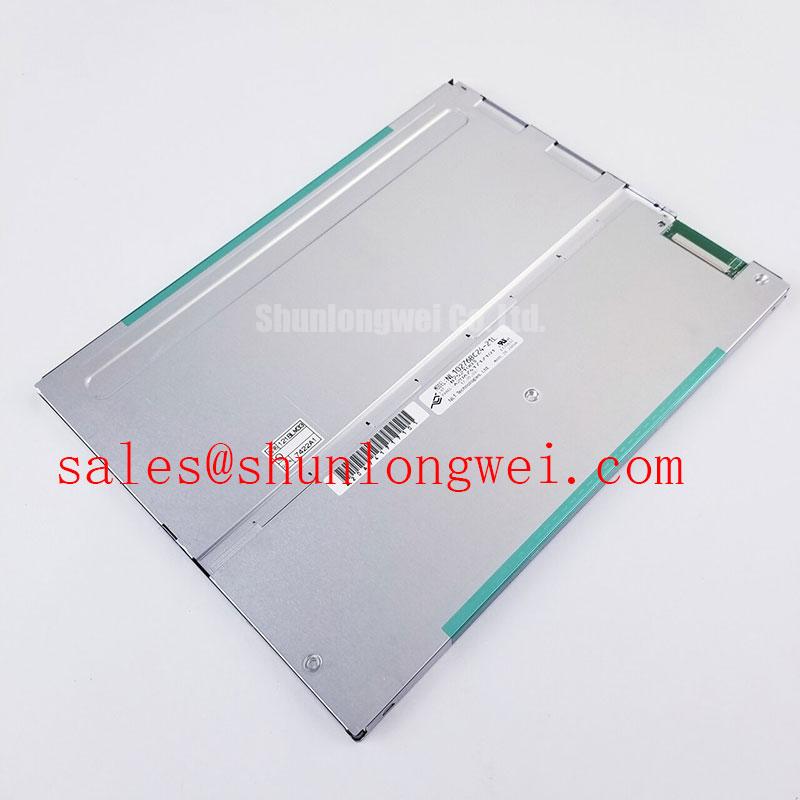
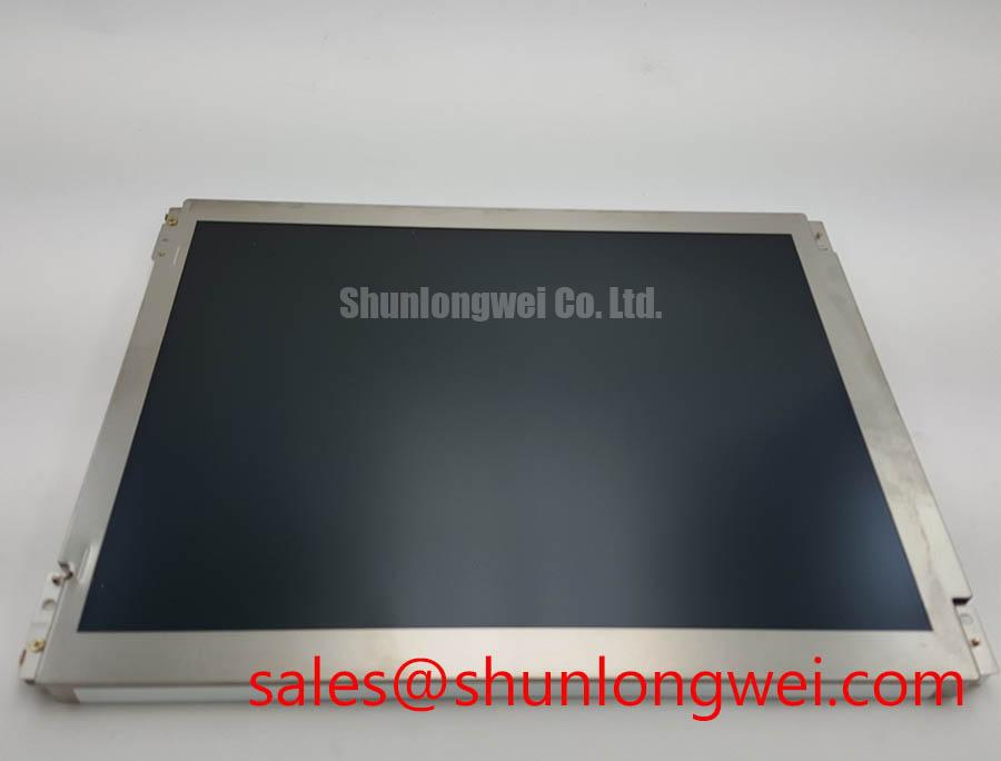
When an industrial HMI shows a dim image, uneven illumination, or intermittent video, isolate the display assembly before changing the controller: inspect the panel connector, confirm the logic rail, and compare the active image area with a known good signal path. The NEC NL10276BC16-01 is an 8.4-inch XGA LCD display with a 1024 × 768 pixel resolution, 400 cd/m² typical luminance, and a 1-channel LVDS interface.
Its official operating temperature range is 0°C to +55°C, with a storage range of −20°C to +60°C. The logic supply is 3.3 V DC typical. These values provide primary compatibility checks for industrial control panels, CNC operator interfaces, factory automation terminals, and compact machine monitoring equipment.
The installed backlight architecture is 4 CCFL edge-lit, with a listed lamp life of 50,000 hours, subject to the specified operating conditions and life criterion. This is not a solid-state WLED panel specification, so an integrator should not treat LED constant-current driving, 1000:1 PWM dimming, or LED half-life performance as properties of this exact model. The CCFL system requires an appropriate high-voltage backlight inverter matched to the panel assembly and the original equipment wiring.
During a service inspection, check whether the image remains visible while the backlight is inactive or unstable. A visible raster with poor illumination can direct the investigation toward the backlight circuit, inverter, cable connection, or lamp assembly, while a completely absent raster requires separate verification of the LVDS path and logic supply. Acoustic noise from an inverter should be assessed at the system level rather than attributed to the LCD cell without measurement.
Brightness control should be evaluated through the original equipment interface. A replacement controller that expects LED current regulation or high-frequency PWM may not be electrically compatible with this CCFL-based display. The Backlight Units reference provides useful background on how illumination architecture affects optical uniformity and system integration.
The specified 400:1 contrast ratio and 400 cd/m² typical luminance are the relevant display performance figures supplied for this model. Direct sunlight readability, optical contrast above 500:1 at 50,000 lux, and anti-flicker performance require complete assembly testing with the actual cover glass, bezel, inverter, and ambient lighting. They should not be presented as factory specifications for the panel alone.
Surface Anti-Glare and Anti-Reflective Evaluation for High Ambient Readability
Check the viewing position and surface reflections before changing the display, because glare can be mistaken for insufficient luminance. The NEC NL10276BC16-01 is specified with typical viewing angles of 85° up, 85° down, 85° left, and 85° right at contrast ratio ≥ 10. This symmetric angular specification supports operator viewing from different positions around a machine control enclosure.
The supplied parameters do not identify a specific etched anti-glare or anti-reflective coating, nor do they confirm optical performance under direct sunlight. If the panel is installed behind a protective window, compare the window angle, surface finish, air gap, and surrounding reflections with the original installation. An added cover can change perceived contrast even when the LCD electronics are operating correctly.
| Parameter | NL10276BC16-01 | Integration relevance |
|---|---|---|
| Display size | 8.4 inch, 21 cm | Compact industrial panel cutouts |
| Resolution | 1024 × 768 XGA | Confirm controller timing and image format |
| Luminance | 400 cd/m² typical | Useful reference for indoor industrial lighting |
| Contrast ratio | 400:1 | Compare with the original display condition |
| Viewing angle | 85° / 85° / 85° / 85° typical | Supports symmetric operator viewing |
| Interface | 1-channel LVDS, 6-bit / 8-bit selectable | Controller mapping must match the panel |
| Logic supply | 3.3 V DC typical | Verify the host power rail before connection |
For a same-resolution display assessment, engineers can also review NL10276AC30-53D. It should be treated as a separate evaluation item, not an automatic substitute, until connector position, LVDS mapping, mechanical dimensions, backlight requirements, and controller timing have been checked against the equipment documentation.
Preventing Frame Lag and Image Smearing in Cold Storage and Outdoor Equipment
The official operating range of this display is 0°C to +55°C, while the storage range is −20°C to +60°C. Use the operating range when assessing powered operation; storage temperature is not an operating permission. At low temperatures, liquid crystal response can become slower, producing visible trailing or delayed transitions even when the LVDS data stream remains valid.
For equipment exposed to cold starts, allow the enclosure and panel to reach a stable condition within the specified operating window before judging image response. Condensation control is a system design consideration: enclosure ventilation, sealing, warm-up behavior, and humidity management should be reviewed together. The supplied specifications do not establish operation from −30°C to +85°C, nor do they specify GTG response time, perimeter sealant performance, or an integrated heater strip.
Mechanical installation also affects image quality. The panel should be supported evenly around its mounting points, with the bezel and sealing gasket seated without local compression or twisting. Uneven force can create visible pressure marks, light leakage, or localized mura. ⚠️ Maintenance Note: Inspect the cabinet airflow path and sealing gasket condition during scheduled service so dust buildup and gasket deformation do not increase thermal or mechanical stress.
FPC routing deserves the same care as thermal control. Keep the flexible cable free from sharp folds, repeated movement, and connector side loading. The locking mechanism should be fully engaged before power is applied. If an image intermittently smears, splits, or disappears during vibration, compare the display response with a stationary image source and inspect the cable retention before replacing the panel.
LVDS Data Mapping Alignment and Signal Integrity
Confirm the host controller’s LVDS format before installation. This model uses 1-channel LVDS with selectable 6-bit / 8-bit color support, allowing either 262K or 16.7M color operation when the controller configuration matches the panel. A mismatch between the host and panel bit mappings, such as JEIDA versus VESA, can produce abnormal colors or incorrect grayscale. Confirm the required mapping in the panel documentation rather than assuming that both formats are selectable.
Power sequencing should be checked with the original panel documentation and the controller interface specification. The panel’s stated logic supply is 3.3 V DC typical; do not assume a 5 V rail is acceptable. Observe the supply rise, enable behavior, and LVDS activity with appropriate measurement equipment, while keeping the differential pair routing short, balanced, and separated from noisy switching nodes. Differential impedance and termination are system-board design matters that require validation on the actual controller and cable assembly.
When troubleshooting image artifacts, compare the panel mapping configuration, pixel clock behavior, connector orientation, and ground continuity. A stable power rail does not confirm correct data mapping, and a correct mapping table does not compensate for a damaged or poorly retained FPC connection. For a related display solution assessment, NL6448BC33-74E may be reviewed as a separate complementary display option rather than a direct replacement.
Long-term integration work can reference Industrial Display & HMI Solutions when evaluating enclosure design, operator visibility, thermal management, and service access for factory automation equipment.