

Content last revised on September 10, 2026
Industrial Bezel Mechanical Envelope Tolerances and Mounting Screw Torque Optimization
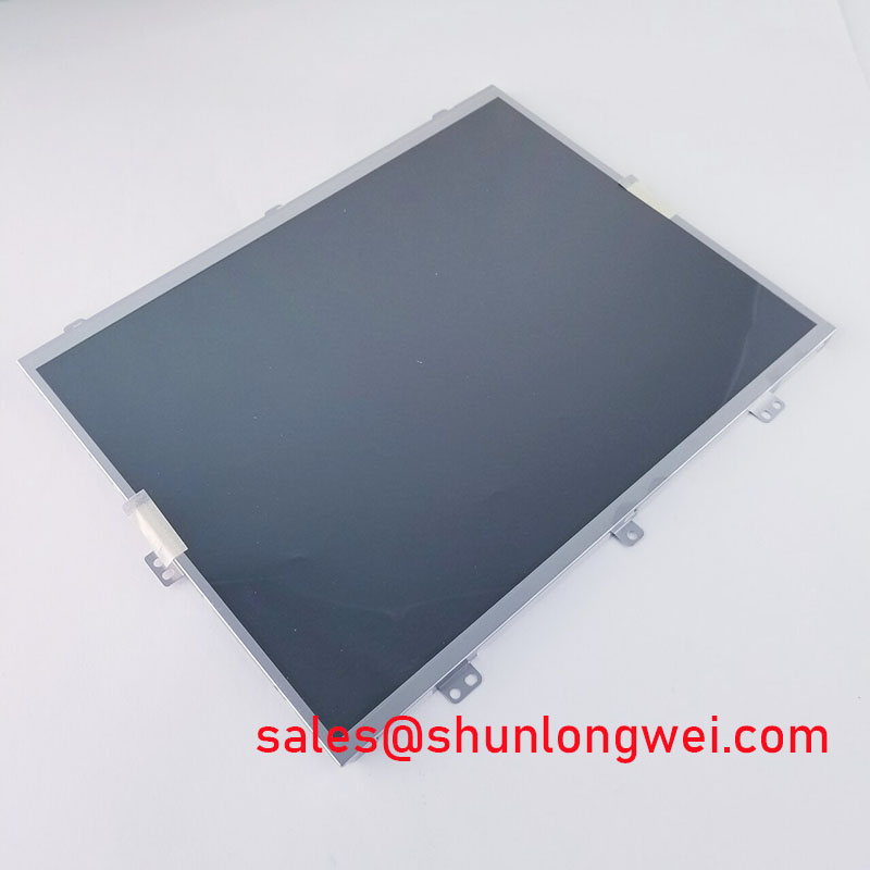
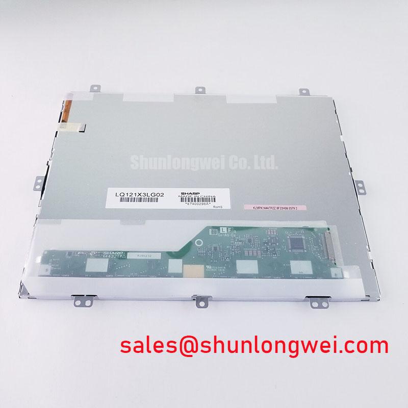
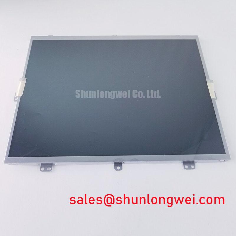
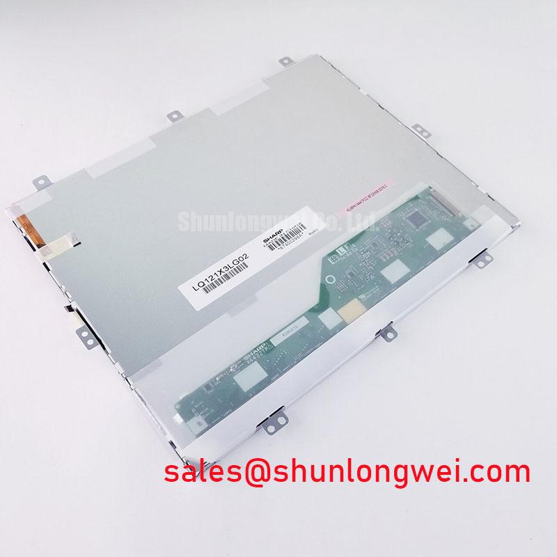
Install the replacement on a clean, flat support surface and inspect the bezel opening for burrs, bent sheet metal, trapped gasket material, or uneven seating points. A TFT LCD module can show optical nonuniformity when the surrounding chassis applies concentrated pressure. This is a system integration concern, not a confirmed factory characteristic of LQ121X3LG02. The bezel should support the assembly evenly while allowing the display frame to remain free from local distortion.
Fasteners should be tightened progressively in a cross pattern so that the frame settles evenly against the mounting surface. The supplied factory information does not specify screw size, fastener torque, chassis tolerance, or allowable bezel compression for this model. Any torque value used during installation must therefore come from the equipment manufacturer’s mechanical drawing or the approved service procedure. If no such instruction exists, the maintenance team should establish a controlled starting point on a nonproduction fixture and inspect the display under a uniform test image after tightening.
Check the panel in dark, mid grey, and full white test fields. Localized brightening, dark patches, or changes that appear only after the bezel is secured may indicate mechanical loading, frame distortion, or an uneven gasket interface. These observations do not establish a single fault cause. Release the fasteners in a controlled sequence, inspect the contact surfaces, and compare the optical result with the panel in an unloaded condition.
Backlight service decisions also require documentation. The available verified data does not state whether this exact assembly uses a particular lamp or LED arrangement, nor does it provide a brightness decay curve, MTBF value, half brightness lifetime, or constant current requirement. A claimed lifetime figure should not be assigned to LQ121X3LG02 without a traceable Sharp specification or an applicable system level reliability document. The original driver, harness, and protection arrangement should be checked as part of the replacement evaluation.
Where a different panel is being considered, the LMS700KF01-001 may be reviewed as a separate engineering comparison. It should not be treated as a drop in replacement until its outline, optical area, connector, timing, power requirements, and mounting details have been checked against the host equipment.
⚠️ Maintenance Note: Inspect the cabinet airflow path and the condition of the display gasket during scheduled service, because dust buildup and degraded sealing can increase contamination and thermal stress around the display assembly.
Shielded FFC or FPC Cable Grounding across Connector Shells
After the mechanical fit is confirmed, inspect the flexible cable route without bending or twisting the cable at the connector entrance. The verified product data supplied here does not identify the LQ121X3LG02 signal interface as LVDS, TTL, or another specific electrical format. It also does not provide a connector drawing, pinout, differential impedance, clock specification, skew limit, shield construction, or grounding method. The replacement cable must therefore be selected from the original equipment documentation.
In an industrial cabinet containing variable frequency drives or other high energy switching equipment, cable routing is a system level design consideration. Keep display signal wiring separated from motor output conductors and switching power paths where the cabinet layout permits. Maintain the intended reference connection at the equipment interface, avoid accidental shield pigtails that are not supported by the original design, and verify that the cable shield and connector shell make the contact intended by the equipment drawing.
Horizontal noise bands, intermittent pixels, unstable graphics, or a display that changes when nearby equipment switches may have several possible causes. Inspect the flexible cable for crease marks, contamination, incomplete insertion, latch damage, and strain at the connector. Then compare the signal at the display input with a known good assembly or a controlled test source. An oscilloscope can help identify ringing, common mode disturbance, loss of differential balance, or timing instability, but the measured limits must come from the applicable interface specification rather than from an assumed value.
If the host documentation confirms a differential display link, the system designer may evaluate the complete channel impedance, pair symmetry, return path, connector transition, and cable length. A commonly used 100 ohm differential design target may apply to some interfaces, but it is not an official specification confirmed for LQ121X3LG02 in the supplied data. The same caution applies to clock skew and jitter limits. These values are determined by the controller, cable, receiver, and interface standard used by the host system.
Ferrite components should be considered only after the interference path has been identified. Adding a common mode component without checking its effect on signal integrity can alter the channel response or create a new voltage drop. Engineers should validate any suppression component during power sequencing, display refresh, brightness changes, and nearby drive switching. Record the cable orientation and grounding arrangement that passes the system test so that future service replacements remain consistent.
Backlight Drive and Flicker Evaluation for Industrial Display Service
Do not connect an unverified backlight supply to the replacement module. The available factory information confirms the assembly category but does not disclose the backlight source, input voltage, current requirement, dimming method, PWM frequency, optical output, or lifetime rating. The system integrator should verify the required supply and control signals from the original panel documentation before energizing the unit.
When the original equipment uses a dedicated backlight driver, inspect the driver output, enable timing, current regulation, connector condition, and protective shutdown behavior. A dark screen may originate in the backlight path, the display controller, the signal cable, or the panel itself. Separating these paths with controlled measurements is more reliable than replacing several assemblies at once. Record the result of a low brightness test, a full brightness test, and a static test image while monitoring for flicker or intermittent shutdown.
Flicker evaluation should consider both the driver and the camera or optical instrument used for inspection. A display can appear stable to the eye while showing modulation in a recorded image, while a camera can also introduce rolling shutter artifacts. Confirm the result with the approved service test method. If PWM dimming is part of the original system, verify that its frequency and duty control are compatible with the display driver and controller. Do not assume a 1000:1 dimming ratio or a specific 200 Hz to 1 kHz operating range for LQ121X3LG02 because those values are not present in the verified factory information.
Ambient light evaluation is also application dependent. A railway passenger information terminal or cab signalling display may require a specific optical performance level under its enclosure, window, and viewing geometry. The supplied data does not confirm a contrast ratio, anti glare coating, sunlight readability rating, or illuminance test condition for this Sharp module. The equipment owner should define the acceptance image and lighting condition, then compare the replacement with the removed panel using the same optical setup.
For a display chain that includes a separate controller or backlight subsystem, the LQ9D03B can be reviewed as a related display solution during system level planning. Its presence does not establish electrical compatibility with LQ121X3LG02. Pinout, voltage, timing, driver behavior, and mechanical fit must be verified independently before any cross reference is approved.
Heat Spreader Placement along Narrow Display Edges
Thermal inspection should begin with the installed panel operating in the same enclosure and brightness condition used by the equipment. Check for blocked vents, compressed seals, contact with hot chassis parts, and heat conducted into one edge of the display frame. The factory information supplied for LQ121X3LG02 does not include thermal resistance, permitted case temperature, heat spreader dimensions, LED lifetime data, or an L70 or B50 rating. These values must not be presented as model specific guarantees.
An aluminum rail or other heat spreading feature may be considered when the cabinet design produces a localized temperature gradient. This is a Design Consideration, not a confirmed construction detail of the Sharp module. The spreader should not press directly against the active display area, obstruct the intended mounting compliance, or create a new conductive path to exposed electrical contacts. Its effectiveness should be checked with temperature measurements taken at several points around the bezel and rear assembly during representative operation.
Thermal results should be compared before and after enclosure changes, with the same input image, backlight setting, airflow condition, and cabinet configuration. A warm edge does not by itself prove optical material degradation or a backlight defect. Inspect the display for changes in uniformity, color balance, startup behavior, and image retention while correlating those observations with measured temperatures and driver operation.
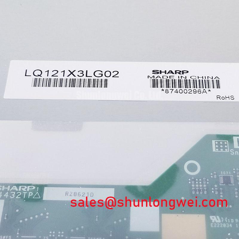
Long term service planning should retain the original panel documentation, cable drawing, backlight instructions, and acceptance image with the maintenance record. The The Ultimate Guide to Industrial TFT LCD Technology provides broader background for reviewing TFT display interfaces, selection factors, and common integration assumptions. For LQ121X3LG02, final approval remains dependent on matching the Sharp model marking and verifying the host equipment’s electrical, optical, and mechanical requirements.