

Content last revised on September 14, 2026
Constant Luminance Output Control and Backlight Reliability Verification
Start the backlight assessment with the driver topology used in the original display assembly. The available factory information for LQ12S41 does not confirm the LED configuration, constant-current input range, dimming method, optical brightness, L70 value, B50 value, or a backlight service-life rating. These values must be taken from the original panel documentation or a manufacturer-issued datasheet rather than inferred from the Sharp model reference.
In an industrial HMI, uneven luminance may be caused by the panel, the backlight driver, the optical stack, supply instability, or a damaged connector. A practical bench check is to operate the display with the approved host electronics and inspect the image at several brightness settings. Record whether brightness changes smoothly, whether one edge appears darker, and whether any area develops a localized hot spot after thermal stabilization. This observation is useful for screening, but it is not a substitute for a calibrated photometric test.
Where the display is installed behind a narrow metal bezel, the mechanical design should avoid trapping heat along the panel edges. As a Design Consideration, an enclosure may require a controlled thermal path or a heat spreader arrangement, but the material, thickness, contact pressure, and mounting method must be established from the complete assembly design. Do not assume that an aluminum rail, adhesive layer, or bezel contact is approved for this model without checking clearance and pressure limits.
If the backlight uses constant-current operation, it should be verified at the driver output and at the panel connector. The system integrator should confirm whether brightness is controlled through a dedicated enable signal, a dimming input, a serial command, or another host-specific method. The LQ12S41 factory context supplied here does not identify that control interface. If a repair substitutes the driver while retaining the display, the engineer should compare current regulation, startup behavior, fault handling, and thermal rise with the original assembly.
Long-term static screen use also deserves attention. A fixed alarm page, machine diagram, or status bar can experience image retention depending on panel construction, drive conditions, temperature, and operating pattern. This page does not assign a guaranteed burn-in or retention limit to LQ12S41. For equipment that displays a stable image for extended periods, designers should consider periodic screen updates, balanced graphic placement, and a controlled brightness level, then validate the result on the actual panel under the intended duty cycle.
LVDS Timing, Pixel Clock and Connector Compatibility
Do not connect the replacement until the original cable and connector have been photographed and documented. The available factory specification does not confirm whether LQ12S41 uses a 20-pin, 30-pin, TTL, LVDS, or another host interface. It also does not state the logic supply voltage, pixel clock range, data format, connector pinout, or backlight pin definition. The system integrator should verify the required supply voltage from the original panel documentation.
When the host uses differential LVDS, the practical compatibility checks include lane count, clock polarity, pair assignment, connector keying, cable orientation, and signal mapping. JEIDA and VESA formats are not interchangeable assumptions. A panel with an otherwise suitable resolution can show incorrect colors, split images, unstable synchronization, or no image when the data mapping differs from the source board. These symptoms require comparison with a known-good signal path and an oscilloscope or suitable high-speed diagnostic instrument, rather than a single-cause conclusion.
Route differential pairs as a controlled transmission structure appropriate to the host board and cable assembly. The commonly used 100 ohm differential target is a Design Consideration, not an official LQ12S41 specification in the information provided here. The PCB stack-up, flex cable, connector transition, return path, and receiver requirements determine the actual implementation. Designers should keep pair geometry consistent, limit unnecessary stubs, and verify eye opening and timing at the panel-side connector.
Power sequencing is another frequent source of field confusion. The host controller should follow the original panel documentation for logic supply rise, reset behavior, display enable timing, backlight enable timing, and shutdown order. A panel that is powered while its control signals are undefined may produce a white screen, unstable startup, or residual image symptoms. These observations do not identify a failed panel by themselves; inspect the supply waveform, enable state, cable seating, and source-board output before replacing additional hardware.
FPC handling is part of electrical reliability. Avoid sharp folds, repeated flexing close to the connector body, and lateral force on the locking mechanism. The bending radius, insertion cycle capability, and connector retention force are not stated in the supplied LQ12S41 factory parameters, so they should be confirmed from the original assembly drawing or connector documentation. During service, release the connector lock fully, insert the FPC squarely, and inspect exposed contacts for contamination before closing the latch.
⚠️ Field Alert: Disconnect system power and allow the host board to discharge before inserting or removing the display FPC.
For a replacement study involving a different display family, engineers may review LM190E08-TLG6 as a separate selection reference, but its connector, timing, optical, and mechanical characteristics must be compared independently rather than treated as an automatic substitute for LQ12S41.
Eye Diagram Margin and Differential Noise in Vibration Bays
A display installed in a vibrating equipment cabin experiences both electrical and mechanical stress. The LQ12S41 specification context identifies the module category but does not provide vibration, shock, EMC, cable-retention, or connector-cycle ratings. For a telematics display used in a heavy mining shovel or earthmoving machine, the complete installation should be assessed, including the display bracket, bezel, cable route, grounding scheme, and host controller.
Begin troubleshooting by comparing the panel-side signal with a known-good unit or an approved reference waveform. Look for intermittent clock loss, changing common-mode behavior, degraded eye opening, and noise that changes when the cable is moved within its permitted service position. Horizontal bands or pixel jitter can arise from signal integrity, grounding, power supply ripple, connector contact, or controller timing. Verification should therefore proceed from the source board through the cable and into the panel connector.
A shielded FFC or LVDS cable may help control radiated and conducted interference when it is compatible with the original mechanical layout. Shield termination is system-dependent: bonding at the wrong point can create unwanted return currents, while an incomplete shield can leave the differential pair exposed to nearby switching fields. Engineers should define the current return path, chassis relationship, and cable strain relief before selecting a grounding method.
Ferrite components are also application-specific. A common-mode ferrite can attenuate unwanted noise, but its impedance characteristics, placement, and effect on the intended signal must be measured on the complete cable assembly. This is a Design Consideration, not a guaranteed LQ12S41 requirement. Do not claim that the display itself has passed a complete machine-level EMC test; compliance belongs to the finished equipment and its validated installation.
Mechanical retention should be checked after thermal and vibration testing. A connector that appears electrically sound on the bench may lose contact pressure when the cable is pulled by a tight bend or when the bracket transmits repeated movement into the panel edge. Use the original strain-relief arrangement where possible, and ensure that the bezel supports the module without concentrating force on the glass or connector area. The correct fastener method, gasket compression, and bracket stiffness must be determined from the enclosure drawing.
The companion device LM64P10 may be relevant when reviewing a related display or backlight topology, but it should not be assumed to provide the correct driver or interface for LQ12S41. Confirm voltage, current, control signals, connector arrangement, and timing from the applicable documentation.
Temperature Evaluation and Liquid Crystal Response
The supplied official parameter set does not state an operating temperature range, storage temperature range, gray-to-gray response time, contrast ratio, sunlight readability value, anti-glare treatment, seal construction, or thermal-cycle qualification for LQ12S41. The frequently cited range of −30°C to +85°C must not be assigned to this model without a supporting factory document. Engineers evaluating a sub-zero or high-temperature enclosure should obtain the original environmental specification and test the complete display assembly at the intended limits.
At low temperature, liquid crystal response can become slower and moving graphics may show additional trailing. That behavior is influenced by the panel construction, drive waveform, temperature history, refresh conditions, and host image content. A practical evaluation should display a repeatable motion pattern while monitoring response, synchronization, brightness, and startup behavior. If the image remains pale, delayed, or unstable, compare the panel supply and timing signals before attributing the behavior solely to liquid crystal viscosity.
High temperature introduces a different set of checks. Inspect the bezel, mounting points, cable exit, and nearby heat sources for expansion-related stress. The enclosure should provide suitable clearance and avoid transferring concentrated force into the module. Any sealant, gasket, or adhesive used in the system must be selected and validated by the equipment designer; the available LQ12S41 information does not verify a particular perimeter sealing material or thermal-cycle performance.
Sunlight and optical performance should be measured rather than assumed. The supplied data does not verify a contrast ratio above 500:1 at a specified illumination level, nor does it confirm an anti-glare coating. For an outdoor-facing operator display, test readability at the actual viewing angle, ambient light, cover material, brightness setting, and contamination condition. A hood or protective window can change reflections and thermal loading, so it belongs in the optical and environmental validation.
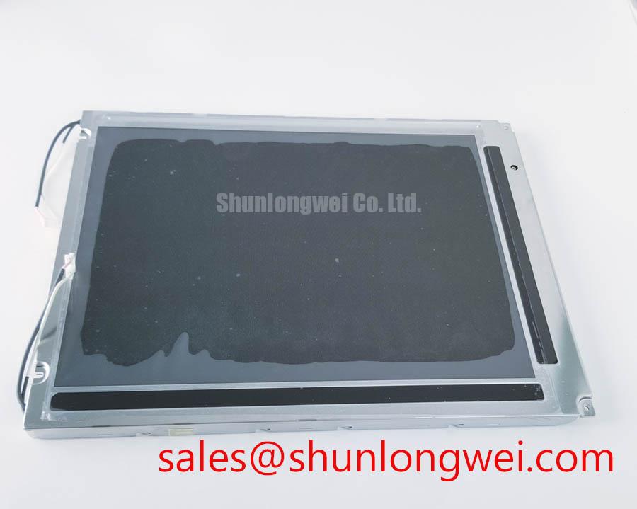
Before approving the panel for a replacement program, record the original module dimensions, active-area position, mounting-hole pattern, connector location, cable exit direction, and front-surface relationship. These physical details determine whether the LQ12S41 can be installed without stressing the FPC or changing the operator viewing position. For broader selection guidance, engineers can consult The Ultimate Guide to Industrial TFT LCD Technology while keeping the final decision tied to the original equipment documentation and measured interface compatibility.