

Content last revised on October 18, 2026
NL6448BC33-31D Replacement Inspection
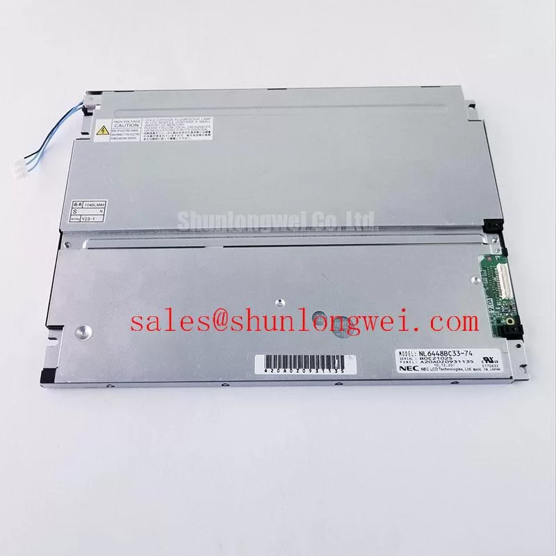
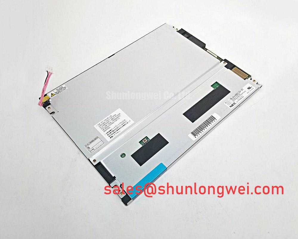
When a replacement panel arrives from a surgical navigation or ultrasound display, first isolate the display assembly, discharge the host equipment, and inspect the connector alignment before applying power. The NL6448BC33-31D is identified as a NEC TFT-LCD active-matrix color display module in an industrial-grade LCD/HMI panel format. Its listing classification is Decoded Baseline / Standard Form Factor; the exact electrical limits, interface timing, optical data, and mechanical drawing should be matched with the original panel documentation before installation.
For incoming inspection, record the panel label, connector condition, visible glass damage, and bezel fit against the removed unit. A replacement evaluation should also compare the host controller output, backlight arrangement, mounting points, and cable orientation. The NEC Display Solutions resource provides useful manufacturer-level context for display integration, while this product page focuses on practical replacement and bench verification of the NL6448BC33-31D.
Radiated Emissions Compliance (CISPR Class A/B) via Backplate Multi-Point Star Grounding
Noise investigation should begin at the complete display assembly rather than at the panel glass alone. In a cabinet containing a variable-frequency motor drive, observe whether pixel jitter, horizontal noise bands, or intermittent image movement changes when the display cable is repositioned. This comparison helps separate a signal-integrity problem from a mechanical connector fault or a system-level radiated-noise issue.
For an LVDS or TTL-based host interface, the transmitter clock, data relationship, and receiver hold margin must remain stable across the intended industrial temperature range. The NL6448BC33-31D should therefore be evaluated with the original controller, cable, and backlight wiring as a complete signal path. Do not assume that a visually similar cable has the same conductor order, shield termination, or return-current behavior.
A backplate grounding strategy can use a controlled star arrangement between the display shield, cabinet reference, controller ground, and cable shield termination. This is a Design Consideration, not an official product certification for the panel. The objective is to control common-mode current and reduce coupling into the display data pair. Where a shielded FFC or LVDS cable is used, inspect the full termination path rather than relying on a short pigtail connected at only one point.
Common-mode ferrite components may be evaluated by the system designer when conducted or radiated noise remains after cable routing and grounding have been checked. Their effect should be confirmed with the actual transmitter edge rate and cable assembly, since an unsuitable component can alter signal quality. CISPR Class A or Class B performance belongs to the completed equipment and enclosure; the LCD module itself should not be described as independently certified to an EMC limit.
VESA vs. JEIDA Data Mapping Alignment & Even/Odd Channel Signal Integrity
Split-screen images, exchanged colors, or unstable vertical sections require a direct comparison between the controller mapping and the panel interface convention. Check the even and odd channel assignments, bit order, clock polarity, and any VESA or JEIDA selection used by the host board. A mapping mismatch can produce a clean but incorrect image, so a continuity test alone is not sufficient.
The host power sequence should be reviewed with the panel documentation before the display cable is connected. Confirm the logic supply requirement, enable relationship, reset behavior, and backlight enable timing from the original system record. The panel category and manufacturer identification do not by themselves establish a universal supply voltage or timing profile. During bench testing, monitor the supply rise and fall behavior while checking for white-screen startup, residual images, or a display that remains active after shutdown.
For differential routing, maintain a consistent pair geometry and a continuous return path through the cable transition. The characteristic impedance target is determined by the controller, cable, and receiver interface, so the system engineer should verify it against the known-good assembly rather than applying a generic value. Oscilloscope measurements at the receiving end are more useful than probing an exposed cable section that does not represent the installed electrical environment.
Backlight operation should be checked independently from image data. A panel can display a valid test pattern while the backlight driver is outside its expected operating condition. When evaluating long-duration use, record brightness drift and thermal behavior under the actual constant-current driver. A claimed lifetime curve, including any 50% brightness point, must come from the applicable backlight specification rather than being assigned to the NL6448BC33-31D solely from its LCD category.
For a possible same-size or same-resolution replacement review, compare the complete connector and timing requirements before considering NL6448BC33-64. Similar model naming does not establish pin compatibility, optical equivalence, or drop-in interchangeability.
Full-Screen Primary Color AOI Screening: Stuck Sub-Pixels & Background Uniformity Audit
Run the incoming inspection with full-screen red, green, blue, white, black, and neutral-gray patterns. The primary-color sequence makes stuck sub-pixels easier to separate from dust, surface marks, and illumination irregularities. Inspect the whole active area at normal viewing distance first, then use controlled close inspection to document the position and appearance of any persistent pixel anomaly.
A 45-degree flashlight check can help distinguish a surface reflection or localized shadow from a defect that remains fixed with the displayed pattern. If a line changes with cable movement, temperature, or gentle frame pressure, stop mechanical manipulation and document the condition; this may indicate an interconnect or panel-edge issue rather than a simple stuck sub-pixel. The result should be compared with the buyer’s acceptance criteria and the original equipment maintenance standard.
Uniformity testing should cover the center, corners, narrow edge regions, and areas close to the backlight boundary. Use the same camera exposure and ambient lighting for before-and-after comparison. Direct sunlight can reduce perceived contrast and conceal low-level non-uniformity, so optical evaluation should be performed under controlled illumination before the panel is approved for a high-precision diagnostic display.
Wide-viewing-angle claims, IPS or MVA classification, anti-glare treatment, and contrast performance must be confirmed from the exact panel documentation. These characteristics should not be inferred from the NEC brand or from the general TFT-LCD category. When a medical imaging console is involved, evaluate grayscale visibility, color consistency, and viewing-angle behavior at the operator’s actual position rather than relying on a centered bench observation.
💡 Bench Tip: Use ESD protection and keep the flat-flex cable perfectly parallel to the connector before closing the lock, because uneven insertion can create intermittent image faults that are difficult to reproduce after reassembly.
Managing Localized Thermal Gradients and Potential Optical Color Shift
Thermal inspection should focus on the narrow display edges, backlight driver area, cable entry, and nearby cabinet surfaces. A localized hot region can change perceived color balance even when the image data remains correct. Compare the panel after warm-up with the same unit at room temperature, and record whether yellowing, edge shading, or brightness variation follows the display assembly or remains with the host electronics.
An aluminum heat-spreader rail may be considered when the enclosure creates a concentrated thermal region, but its dimensions, contact pressure, insulation, and mounting method are system decisions. The rail must not distort the bezel or load the glass. Designers should verify thermal behavior with the completed enclosure and avoid treating a generic spreader as an official feature of the NL6448BC33-31D.
PWM backlight control also requires coordination between the panel assembly and its driver. Check the driver’s switching frequency, duty-cycle linearity, enable timing, and acoustic behavior with the actual load. Flicker perception and visible banding can vary with camera shutter, operator movement, and display brightness, so use both an instrumented check and direct visual inspection. A brightness setting that appears stable on a bench may behave differently inside a sealed HMI enclosure.
Optical bonding, sealing, and dust protection are enclosure-level integration matters. If the replacement is considered for a surgical navigation or ultrasound diagnostic display, verify the front stack, gasket compression, cleaning compatibility, and condensation control against the equipment service specification. The NL10276AC30-53D may be reviewed as a separate NEC display solution within a related system evaluation, but it should not be treated as an automatic electrical or mechanical substitute.
For broader repair planning, the Industrial Display & HMI Solutions reference can support enclosure, installation, and harsh-environment assessment. Final acceptance of the NL6448BC33-31D should be based on verified connector fit, correct host mapping, stable power sequencing, full-screen optical screening, and temperature behavior in the target equipment.