



Content last revised on September 10, 2026
NEC NL6448BC33-64R Industrial LCD HMI Display Module
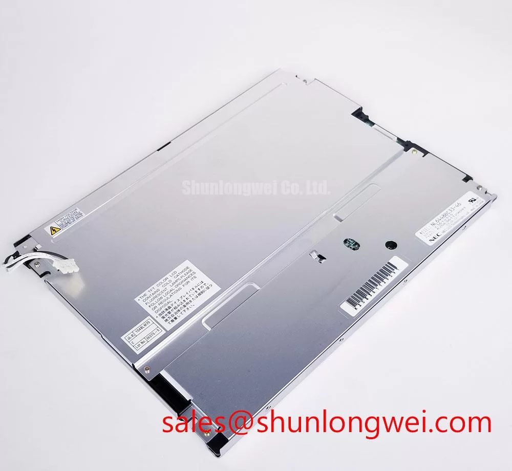
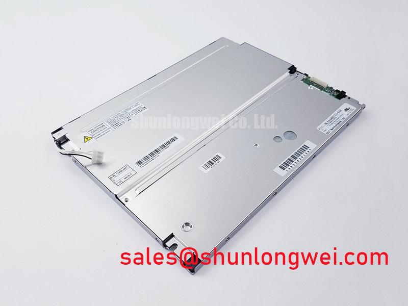
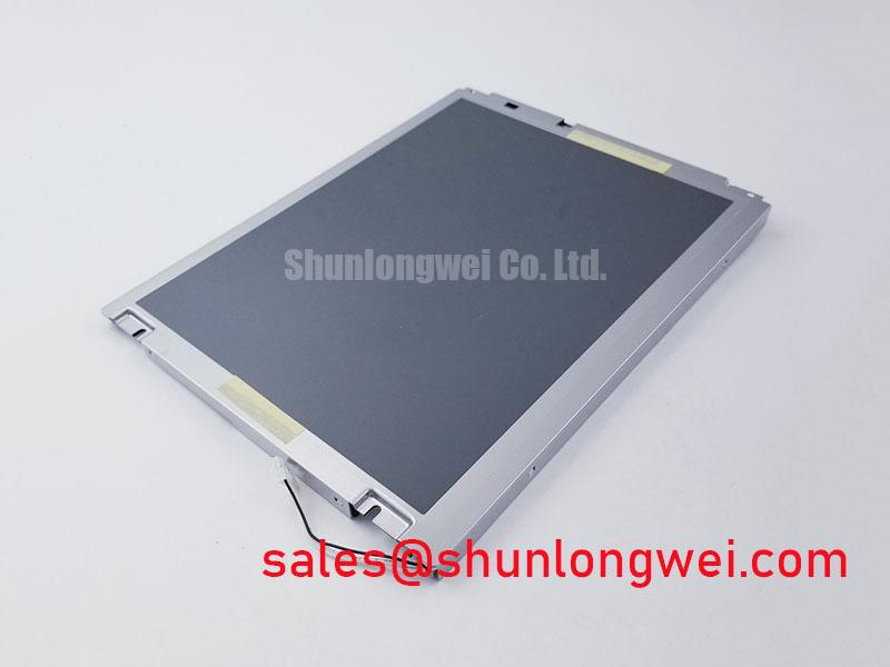
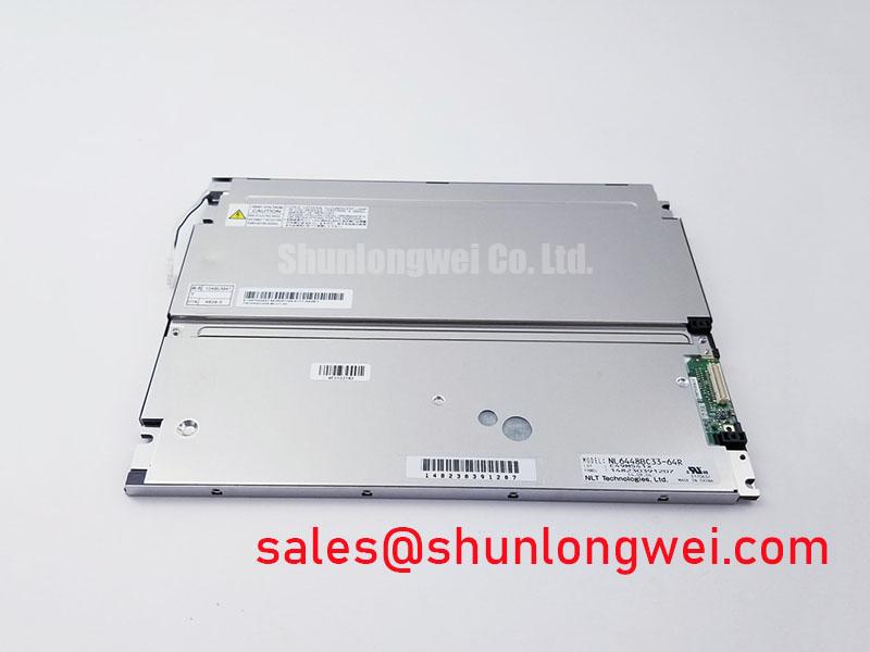
Start incoming inspection by checking the NEC NL6448BC33-64R module label against the purchase record, then examine the TFT LCD glass, frame, connector area, and cable surfaces under controlled lighting before applying power. Record any visible scratches, pressure marks, contamination, frame distortion, or connector damage before continuing with electrical and optical checks.
The NL6448BC33-64R is identified in the supplied factory context as an Industrial Grade LCD/HMI Panel manufactured by NEC. Its package classification is a TFT-LCD Display Module, and its specification status is listed as Official Factory Spec Verified. These points define the confirmed product identity. Resolution, active area, interface assignment, backlight configuration, viewing angle, luminance, contrast ratio, operating temperature, and power requirements should be taken from the original NEC documentation or the panel documentation used in the host equipment.
| Parameter | Confirmed information |
|---|---|
| Model | NL6448BC33-64R |
| Manufacturer | NEC |
| Product category | Industrial Grade LCD/HMI Panel |
| Construction classification | TFT-LCD Display Module |
| Specification status | Official Factory Spec Verified |
For repair purchasing, the part number should be matched with the failed panel’s electrical interface and mechanical installation points rather than with screen appearance alone. A replacement that appears identical can still require a different controller configuration, cable orientation, backlight driver, or power sequence. The system integrator should verify the required supply voltage from the original panel documentation. Do not apply an assumed logic voltage or backlight drive method to an unidentified connector.
High-Voltage Striking Potential and Secondary-Coil Insulation Testing
Before investigating a dark screen, separate the display module’s logic path from its backlight path. A visible image with no illumination points the inspection toward the backlight circuit, inverter or driver, connector seating, and enable control. A completely blank screen requires a wider check that includes the host controller, logic supply, timing signals, cable continuity, and panel response. This prevents a backlight fault from being misreported as a failed LCD cell assembly.
The supplied factory information does not confirm whether a particular installation of the NL6448BC33-64R uses a cold-cathode fluorescent backlight, an LED backlight, or a specific driver topology. The integrator should verify the backlight technology from the original equipment service documentation and the panel label. High voltage must never be inferred from the model name. If the installed system uses a high-voltage inverter, inspect the secondary wiring, transformer insulation, connector housing, and spacing around the lamp circuit using the equipment manufacturer’s approved isolation procedure.
For an LED-driven installation, evaluate the constant-current driver, enable signal, fault feedback, and dimming control as a complete circuit. A PWM command may be present while the driver remains latched off because of open-load detection, overtemperature protection, or an abnormal feedback signal. The correct PWM frequency and duty-cycle limits are system-dependent unless explicitly stated in the panel documentation. Measure the command waveform at the driver input and compare it with a known-good unit before changing firmware or controller settings.
Acoustic noise, intermittent illumination, and brightness modulation should be investigated with both an oscilloscope and a controlled visual test. Check whether the sound changes with brightness demand, line voltage, or enclosure temperature. This observation can help distinguish mechanical vibration in a driver assembly from an unstable control signal, but it does not by itself establish a failed panel. A replacement decision should follow connector inspection, driver verification, and a stable test with the correct host electronics.
Bench Tip: Protect the panel from ESD and keep the flex cable perfectly level while closing its locking actuator; an angled insertion can create intermittent contact that is easily mistaken for a defective display.
Edge Backlight Thermal Dissipation and Optical Surface Preservation
When the NL6448BC33-64R is evaluated for an operator station or monitoring terminal, inspect the complete optical stack as an assembled system. Look for uneven illumination, localized bright zones, dark edges, color shift, haze, and contamination visible on a white test screen. A full-screen red, green, blue, white, and black sequence makes stuck pixels, nonuniform luminance, and localized shading easier to document than a normal operating screen.
The supplied factory parameter set does not verify a particular optical guide material, edge rail construction, luminance rating, or half-brightness life value for this model. Do not attribute a specific thermal limit or LED lifetime to the NL6448BC33-64R without the applicable NEC datasheet. As a Design Consideration, the enclosure should provide a controlled path for heat from the backlight driver and surrounding electronics, while avoiding pressure on the LCD frame or optical layers.
Thermal inspection is most useful when performed during a repeatable display test. Record the ambient condition, image pattern, brightness command, and time from startup. Compare the left and right edges, connector region, and driver location for abnormal temperature differences. A thermal gradient can be influenced by the enclosure, mounting bracket, airflow, driver setting, or cable routing, so the observation should be confirmed after the module is installed in the intended housing.
Optical bonding is an integration choice, not a confirmed construction feature of this display module. If the host equipment uses a bonded cover lens, the engineer should verify adhesive compatibility, optical clarity, serviceability, sealing method, and thermal expansion behavior with the enclosure supplier. A sealed front assembly can reduce dust ingress, but its final environmental performance belongs to the complete HMI construction and cannot be claimed for the LCD module alone.
For a hazardous petrochemical Zone 2 operator station, the display should be evaluated as part of the certified enclosure and control system. The NL6448BC33-64R itself should not be described as independently explosion-proof or as independently compliant with a complete equipment certification. The enclosure, cable glands, power system, temperature rise, and installation method require separate engineering review by the responsible equipment designer.
Signal quality also deserves attention during a thermal test. Confirm that the host transmitter maintains a clean clock and data waveform at the panel connector across the intended operating range. If the image develops intermittent lines, color blocks, or loss of synchronization as the unit warms, compare the signal at the controller output and panel input. This approach helps identify cable, connector, grounding, or transmitter issues without assigning a single cause to the display assembly.
Wide Temperature Operational Margin and Sub-Zero Display Response
Temperature claims must be taken directly from the original NEC documentation for the exact suffix. The supplied factory context does not provide an operating range, storage range, gray-to-gray response time, contrast specification, or optical lifetime figure for the NL6448BC33-64R. Those values should not be substituted with a generic industrial LCD range. When a panel is considered for outdoor monitoring, process control, or a remote operator terminal, the complete assembly should be tested at the temperatures defined by the host equipment specification.
At low temperature, the visible symptom may be slower image transitions, temporary smearing, delayed backlight startup, or reduced uniformity. At high temperature, contrast, luminance, connector behavior, and controller stability may change. These observations should be recorded against a defined test image and measured after the assembly reaches thermal equilibrium. A cold-start result should be separated from a warm-running result because the two conditions exercise different parts of the system.
For long-term static HMI screens, use a screen-management policy that periodically changes fixed graphic elements where the application permits. Keep alarm and safety information continuously visible when required, but consider relocating noncritical logos, status bars, or fixed icons. Persistent image retention can involve the panel, drive waveform, temperature, brightness setting, and operating pattern. A controlled before-and-after comparison is more useful than treating every residual image as permanent damage.
Wide viewing angle and color consistency should be checked from the actual operator position, not only from a straight-on bench view. Use neutral gray and primary-color test images while viewing from the left, right, above, and below positions relevant to the machine. If the host system adds a cover window, bezel, touch layer, or protective film, repeat the evaluation after assembly because reflections and angular color changes can be introduced by those external parts.
Moisture protection is also an enclosure responsibility. The panel perimeter, flex connections, mounting pressure, ventilation design, and front seal should be reviewed together. The display module’s confirmed classification as a TFT-LCD Display Module does not establish an IP rating or resistance to chemical vapors. For application planning, engineers may consult the Industrial Display & HMI Solutions technical resource while validating the final enclosure independently.
VESA and JEIDA Data Mapping Alignment and Even/Odd Channel Integrity
Begin interface verification with the original controller board and cable drawing. The provided factory data does not confirm the NL6448BC33-64R logic voltage, LVDS mapping, TTL assignment, channel order, connector pinout, power-on timing, or differential impedance requirement. The system integrator should verify these details from the original panel documentation before connecting a replacement. In particular, do not select between possible voltage levels or data mappings by trial and error.
Incorrect JEIDA or VESA mapping can produce color inversion, incorrect grayscale, split-screen effects, swapped red and blue information, or a picture that appears synchronized but is visibly corrupted. Even and odd channel errors may affect only part of the image, which is why a full-screen color ramp and checkerboard pattern should be included in incoming inspection. Compare the observed pattern with the known-good controller configuration and confirm the cable orientation at both ends.
Power sequencing should be measured at the panel connector with the display disconnected when necessary to protect the assembly. Observe logic supply rise, reset behavior, display enable, clock activity, and data activity in the order defined by the source equipment documentation. White-screen startup, a short flash, or residual image after shutdown may involve incorrect sequencing, floating control lines, discharge behavior, or controller firmware. These symptoms require waveform comparison rather than a single-cause diagnosis.
Route high-speed display pairs with consistent geometry and a controlled return path according to the system board design rules. Minimize unnecessary cable length, avoid sharp bends near the connector, and keep noisy switching nodes away from the display interface. The final engineer should verify eye quality, timing margin, and immunity under the actual enclosure and cable arrangement. A display module cannot independently claim compliance with complete equipment EMC requirements.
For repair teams comparing panel options, the NL10276BC16-06 may be reviewed as a separate same-class selection reference, but compatibility must be established from resolution, mechanical dimensions, connector definition, interface timing, backlight requirements, and host firmware. It should not be treated as a drop-in substitute solely because both products belong to the industrial LCD category.
During final acceptance, save photographs of the powered white, black, red, green, and blue screens, record the controller and cable identification, and document the measured supply behavior. This record gives maintenance engineers a repeatable baseline for future service work on operator stations and field monitoring terminals without assigning unsupported performance figures to the NEC NL6448BC33-64R.