

Content last revised on November 7, 2026
Incoming Benchtop Inspection: COG/TAB Anisotropic Conductive Film Integrity
Manufacturer: NEC | Part Number: NL6448BC20-18 | Product Category: Industrial Grade LCD Display | Diagonal Size: 6.5 inch | Resolution: 640 x 480 | Interface: TTL / CMOS | Display Type: TFT-LCD Active Matrix Color Display Module
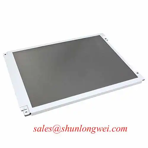
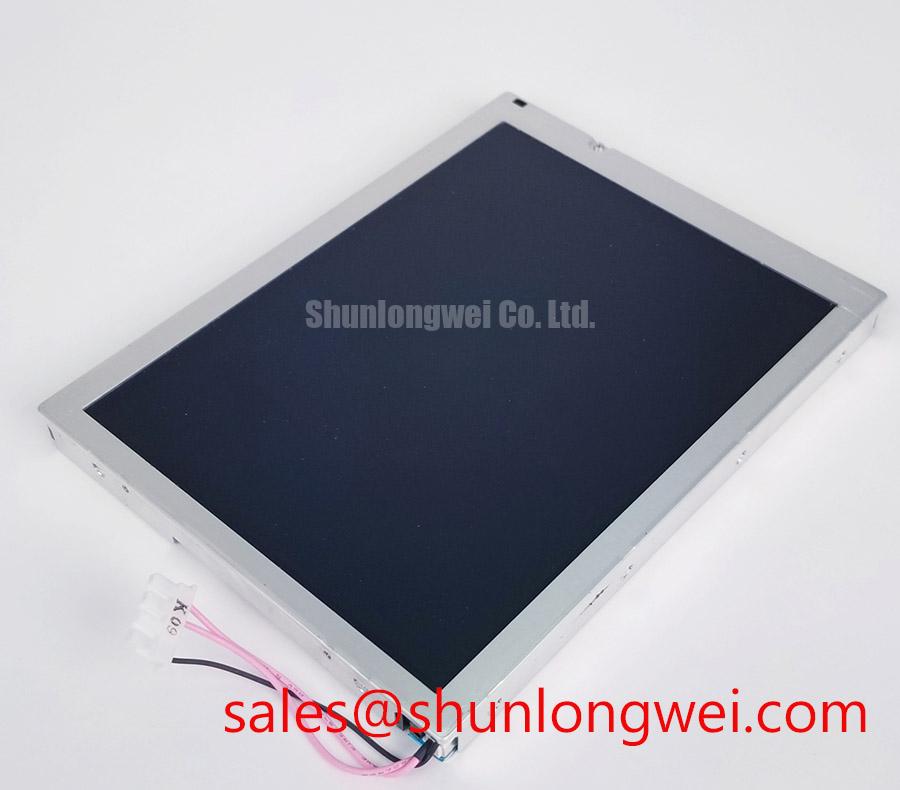
When a machine tool operator terminal arrives with a black screen, intermittent vertical lines, or an uneven image, I start by separating panel faults from signal and backlight faults. The NEC NL6448BC20-18 is a 6.5-inch industrial TFT-LCD module with a native resolution of 640 x 480 pixels and a TTL / CMOS interface. Its compact VGA format makes it relevant when assessing display replacements for existing factory automation HMI equipment.
My first bench check is a controlled visual inspection under uniform illumination. I look along the panel edges for pressure marks, damaged flex connections, contamination around the connector, and visible deformation. I then apply solid red, green, and blue test images. Each primary color exposes a different class of display defect: stuck pixels, missing columns, irregular color bands, or localized image distortion. A white screen helps reveal luminance nonuniformity, while a black screen makes unwanted illumination and leakage easier to observe.
A flashlight held at approximately 45 degrees provides another useful diagnostic view. If image information remains faintly visible while the screen appears dark, the backlight circuit deserves attention. If the illumination is present but the same vertical or horizontal defect remains across test patterns, the investigation should move toward the panel drive path and its connections. COG and TAB bonding faults can produce localized line defects, although visual symptoms alone cannot establish a microscopic bonding failure.
For industrial installations, signal integrity is a separate concern from the panel's physical condition. The NL6448BC20-18 uses TTL / CMOS signaling, so an LVDS differential-pair impedance target must not be imposed on its interface. Designers should preserve the original RGB data, clock, synchronization, and grounding arrangement, keeping signal paths orderly and limiting unnecessary cable length. Where the controller and display are separated by a cable harness, the actual interface timing and electrical loading should guide the layout.
⚠️ Field Alert: Disconnect system power before removing or reseating the display cable to avoid connector damage and unintended electrical stress on the signal interface.
Display Brightness Uniformity & Thermal Management
Uneven brightness across a compact LCD is worth investigating before changing the complete display assembly. I compare the illuminated area from edge to edge, paying particular attention to dark corners, localized bright regions, and changes that appear after the equipment has warmed up. These observations help distinguish an illumination problem from image-processing or liquid-crystal response abnormalities.
Thermal management around a display is primarily an enclosure-level design consideration. The metal mounting frame, adjacent power electronics, and available ventilation all influence the temperature around the panel. When evaluating a replacement for an existing machine-tool operator terminal, I inspect the original mounting arrangement and identify whether heat from nearby components is being transferred directly into the display housing.
An aluminum heat-spreading rail can be considered where enclosure measurements identify localized heating near an illuminated edge. Its dimensions, contact arrangement, and mechanical pressure must be determined from the actual assembly. Excessive clamping pressure is undesirable because the LCD glass and its surrounding connections are sensitive to mechanical stress. A thermal improvement should never introduce additional pressure onto the active display area.
The distinction between TTL and LVDS is particularly important during controller integration. The NL6448BC20-18 is identified with a TTL / CMOS interface; it should not be connected to an LVDS transmitter simply because both interfaces carry digital display data. TTL RGB data, pixel clock, and synchronization signals require compatible controller outputs and appropriate timing. Clock stability, data setup time, and hold time should be evaluated against the actual panel timing requirements.
At elevated ambient temperatures, engineers should also consider the effect of enclosure heating on controller timing and display response. An oscilloscope inspection of the clock and RGB signals can help identify unstable transitions, excessive ringing, or timing inconsistencies. Cable routing should keep display signals away from high-current switching conductors wherever the equipment layout permits.
For industrial display technology context, engineers can consult Tianma Industrial TFT Display Solutions and compare the relevant display technologies and integration requirements. This reference is useful for technology evaluation, not evidence that a particular optical material or LED backlight construction is fitted to the NL6448BC20-18.
Optical Luminance Degradation Curve & CCFL-to-LED Modernization Retrofit Pathways
A display that gradually becomes difficult to read requires an illumination diagnosis before a replacement strategy is selected. I first compare screen brightness across the active area, then observe whether illumination starts consistently after power-up. A dark screen, delayed illumination, uneven brightness, or intermittent flickering can involve the backlight, its power supply, wiring, or the display control system.
One important distinction concerns the exact model suffix. Technical information published for the NL6448BC20-18D identifies a two-lamp CCFL backlight, but the suffix D must not be silently removed when applying those specifications to the NL6448BC20-18. The two part numbers should be treated as distinct procurement and engineering references. In particular, CCFL starting voltage, lamp current, inverter requirements, and luminance figures from the D-version documentation are not automatically specifications for the unsuffixed model.
LED modernization is a possible system-level retrofit consideration when an existing display assembly requires illumination service. It is not an automatic plug-compatible conversion. The engineer must evaluate the physical backlight arrangement, optical uniformity, electrical supply, mounting provisions, and thermal behavior of the proposed retrofit. A constant-current LED driver is a common approach to controlling LED illumination, but its output characteristics must match the selected LED assembly.
PWM dimming can also be considered when the replacement illumination system supports it. The control frequency, duty-cycle behavior, and interaction with the display controller should be checked during actual operation. Visible flicker, camera banding, or interference with other control electronics can depend on the combined system rather than the backlight driver alone. An oscilloscope and a controlled brightness test provide a more useful assessment than assuming that a particular PWM frequency guarantees flicker-free operation.
LED service-life figures require careful interpretation. An L70 rating describes the point at which a specified LED population reaches a defined percentage of initial luminous output under stated test conditions. It is not automatically the operating lifetime of the complete LCD module. Driver temperature, operating current, optical conditions, and enclosure ventilation all influence the installed system. A claimed 50,000-hour operating life or MTBF should therefore not be attributed to the NL6448BC20-18 without a model-specific supporting specification.
When assessing associated display electronics, NL6448BC26-27C can be reviewed as a separate NEC display-family reference. It is not a confirmed backlight driver or electrical accessory for the NL6448BC20-18. The connector arrangement, display dimensions, signal architecture, and power requirements must be assessed independently before considering either model in an equipment redesign.
Contrast, Viewing Angle & Temperature-Dependent Display Behavior
Contrast complaints should be investigated under repeatable viewing conditions. I check the display from the normal operator position, then compare the image at different viewing angles and operating temperatures. A panel that appears washed out from one direction may have a viewing-angle characteristic rather than a defective contrast-control circuit. Similarly, temperature-related changes in grayscale transitions should not immediately be diagnosed as permanent panel damage.
The 640 x 480 resolution of the NL6448BC20-18 provides a conventional VGA image format. During replacement assessment, I check whether the host controller generates the expected image dimensions and whether its RGB signal mapping corresponds to the panel interface. Incorrect color-channel mapping can produce abnormal colors even when the display itself is functioning.
Liquid-crystal optical behavior varies with temperature. Changes in molecular orientation and electro-optical response can influence grayscale transitions, particularly when equipment moves between a cold startup condition and a warmer operating state. The practical test is to compare identical grayscale patterns under controlled conditions while monitoring the enclosure temperature and allowing the display to stabilize.
TN, IPS, and MVA describe different LCD operating technologies and should not be treated as interchangeable panel specifications. Viewing-angle performance, grayscale behavior, and contrast characteristics depend on the actual panel construction. An IPS or MVA replacement should not be assumed to provide identical mounting, timing, optical appearance, or electrical compatibility with an existing TN-based system.
Surface treatment is another consideration when the operator works under bright factory lighting. Reflections from overhead lamps can reduce perceived image clarity even when the display electronics operate normally. Engineers should evaluate the complete front-window and panel arrangement, including ambient reflections and viewing direction. An anti-glare surface treatment may be relevant to a new enclosure design, but its presence must not be assumed for the specified NEC model without confirmation.
When checking a display with apparent grayscale inversion, I compare the same image at different viewing angles and inspect the source video signal for incorrect RGB mapping. If the abnormality remains, the investigation can move toward panel drive behavior and temperature-dependent optical response. This avoids unnecessary changes to the host controller when the actual problem is associated with the display assembly.
For replacement planning, NL6448BC33-59D is another NEC-family display reference worth evaluating, but it is a 10.4-inch-class model rather than a dimensionally identical 6.5-inch replacement. It must not be treated as a direct mechanical drop-in for the NL6448BC20-18. A substitution assessment needs to cover enclosure dimensions, active display area, resolution, interface, connector pinout, supply requirements, and host-controller compatibility.
Long-term display evaluation should include operating temperature, image stability, mounting stress, and the condition of the complete operator terminal. The Integrated by Design Technical Reference provides additional context for evaluating display integration at equipment level, particularly where the display, controller, enclosure, and power architecture are maintained as one system.