Content last revised on October 7, 2026
Display Data Mapping Alignment and Signal Integrity
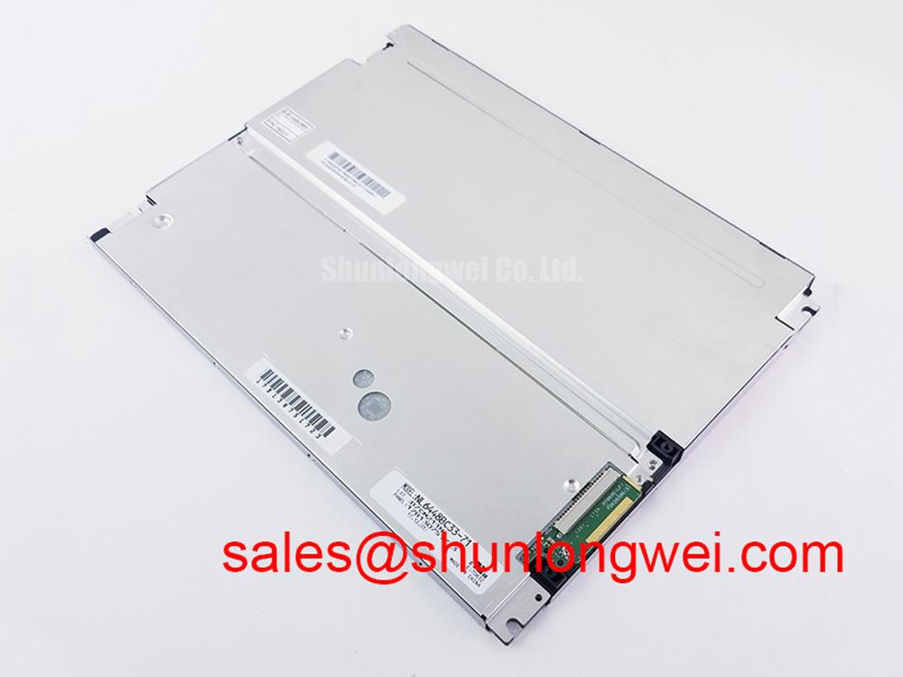
Before installing the display in an AGV or forklift console, inspect the connector, bezel, cushioning interface, and mounting points, then compare the replacement panel against the original equipment documentation. NL6448BC33-70G is identified as a NEC Industrial Grade LCD/HMI Panel using a TFT-LCD Display Module construction. The available factory information confirms the product category, manufacturer, package type, and official specification status; it does not, by itself, confirm every electrical interface, backlight topology, timing value, or operating-temperature limit required by a particular vehicle display assembly.
When replacing a display in an automated guided vehicle or heavy-duty forklift terminal, begin with the original panel documentation and the controller board schematic. Confirm the logic supply requirement, connector pin assignment, signal direction, pixel clock arrangement, and whether the host uses LVDS, TTL, or another display interface. These details must not be inferred from the NL6448BC33-70G model number alone.
JEIDA and VESA data mapping can place color bits in different positions even when the connector appears mechanically compatible. A mapping mismatch may produce incorrect colors, unstable grayscale, split-image behavior, or a display that shows a valid backlight without usable image data. During bench evaluation, compare a known-good panel and the replacement with the same controller, cable, and image pattern. Check the red, green, and blue channel order, even and odd data lanes where applicable, clock polarity, enable signals, and any control lines used by the host system.
A differential display link should be routed with controlled impedance appropriate to the transmitter, receiver, cable, and board stack-up. A nominal 100 Ω differential impedance is a common design consideration for LVDS routing, not a confirmed factory specification for this display module. The system designer should verify the applicable interface standard before changing cable length, connector type, or termination. Keep the signal path continuous, avoid unnecessary adapters, and inspect the shield and return path where the panel is installed near traction motors, contactors, or high-current battery wiring.
Power sequencing also requires confirmation from the original panel documentation. Do not assume that the logic rail is 3.3 V or 5.0 V, and do not apply power until the required voltage and enable order are verified. The timing window supplied in a controller manual may differ from the display manufacturer’s requirements. An oscilloscope check of the logic rail, display enable, pixel clock, and reset behavior is more useful than relying on a visual power-on test alone.
Cold operation can lengthen liquid-crystal response time because viscosity changes with temperature. If a vehicle display becomes visibly slower after overnight exposure to a cold warehouse, record the panel temperature and compare response using a fixed test pattern. A heater strip may be part of the complete equipment design, but its presence, control method, power rating, and thermal limits must be confirmed from the original assembly documentation. The NL6448BC33-70G factory data supplied here does not establish a −20 °C, −30 °C, or other operating-temperature rating.
Backlight Inverter Striking Voltage and Ignition Debugging
Backlight technology must be established before troubleshooting brightness, startup delay, flicker, or audible noise. The supplied product information identifies the unit as a TFT-LCD display module but does not confirm whether a particular assembly uses CCFL, LED, or an external backlight system. The integrator should verify the original panel datasheet, inverter board markings, lamp connectors, and controller interface before applying any high-voltage test procedure.
If the installed assembly uses a dual-channel CCFL inverter, cold ignition behavior belongs to the inverter and lamp assembly rather than being treated as an automatic specification of the display model. High-voltage probing requires equipment rated for the expected waveform and an appropriate safety procedure. Inspect the lamp connectors, insulation, harness routing, grounding points, and inverter feedback circuit. A failed start can result from lamp aging, connector contact resistance, insulation leakage, inverter protection activity, supply instability, or an incorrect enable signal. These possibilities should be separated through measurement rather than assigned to a single cause.
For an LED-backlit configuration, the driver topology, current regulation, dimming method, and thermal arrangement must be verified from the original equipment. Do not assume constant-current operation, a 1000:1 PWM dimming ratio, or a particular PWM frequency without documentation. If the system uses PWM, observe the control signal with an oscilloscope and compare its duty-cycle response with the host command. Visible flicker, uneven brightness, or acoustic noise may involve the driver, mechanical resonance, grounding, or control-loop behavior.
Digital timing faults should be checked at the transmitter and at the panel-side connector. Measure clock stability, data activity, enable timing, and signal integrity while the display is cold and warm. TTL and LVDS are not interchangeable electrical interfaces, and a cable that fits physically may still have incompatible voltage levels or data mapping. Confirm the signal specification before selecting a replacement cable or adapter.
For an emergency service assessment, record the original backlight current, start behavior, brightness uniformity, and image stability before removing the old unit. Then repeat the same observations with the replacement under controlled conditions. This produces useful comparative evidence without assigning unsupported ignition voltage, half-life, MTBF, or service-life values to the NL6448BC33-70G.
Backlight Thermal Dissipation and Optical Stack Preservation
In a rugged vehicle terminal, mechanical installation can affect optical performance as much as the display electronics. Check the bezel for distortion, verify that the panel is supported evenly, and inspect the vibration isolators for compression set, cracking, contamination, or displacement. Excessive local pressure can create visible nonuniformity, especially when the display is clamped against an uneven chassis.
For an LED-backlit assembly, heat must be evaluated across the complete optical and mechanical stack. The edge rail, backlight frame, diffuser, reflector, and rear cover form a thermal path that varies by product design. The available official information does not confirm an aluminum heat spreader, a PMMA light guide plate, a high-nit backlight, L70/B50 performance, or any specific LED lifetime. These features should be verified from the exact panel or backlight documentation instead of being assumed from the display category.
During thermal inspection, use the same image content and brightness command while measuring the driver region, edge rail, rear cover, and nearby seals. Look for localized heating rather than relying only on the average enclosure temperature. A hot spot may be associated with current concentration, poor contact to a spreader, blocked airflow, a damaged diffuser, or an unsuitable replacement driver. The system engineer should determine acceptable temperatures from the component ratings and enclosure test plan.
Optical uniformity should be checked after the panel has reached a stable condition. Use full-white, mid-gray, black, and colored test images to reveal edge brightening, clouding, mura, or channel imbalance. If a forklift display is exposed to dust, oil mist, or cleaning chemicals, inspect the front seal and bezel interface during every service cycle. Fluid ingress can affect the display layers, connector contacts, backlight driver, or touch interface, depending on the complete assembly.
⚠️ Field Alert: Check the anti-vibration pads and perimeter supports during scheduled service; uneven compression or overtightened fasteners can transfer chassis vibration and local stress into the LCD assembly.
Where a technically compatible panel is being evaluated, the engineer may compare the wiring, connector orientation, resolution, and controller requirements with NL10276BC16-06. This is a neutral engineering comparison, not a substitute recommendation. The original equipment designer must confirm mechanical, optical, electrical, and software compatibility before approving any alternate display.
Temperature Operating Margin and Sub-Zero Liquid-Crystal Behavior
Temperature qualification should begin with the actual enclosure and duty cycle rather than with a generic industrial label. The supplied factory information confirms the NEC manufacturer and TFT-LCD Display Module package, but it does not provide a verified −30 °C to +85 °C operating range for this product. Those limits must be taken from the applicable original datasheet or equipment qualification record.
At low temperature, liquid-crystal viscosity can increase and slow gray-to-gray transitions. The practical result may be motion blur, delayed character changes, or temporary image persistence during cold startup. To investigate, place the complete display assembly in a controlled environmental test condition, apply repeatable text and motion patterns, and monitor the panel temperature, supply rails, image timing, and backlight state. Do not treat a temporary cold-start artifact as proof of panel failure without comparing it with the specified response limits.
Condensation control is equally important in AGV and forklift applications. A panel moving from a cold storage area into a humid charging or maintenance area may experience moisture on connectors, the front surface, or internal interfaces. Enclosure ventilation, gasket condition, drain paths, and warm-up procedures should be reviewed by the equipment designer. Sealant composition, perimeter adhesive performance, and thermal-cycle endurance are assembly-specific properties that require documented verification.
Heater control, if used, should be evaluated as part of the complete terminal. Confirm the heater sensor location, switching behavior, clearance from the LCD surface, and interaction with the display power sequence. A heater can reduce cold-start delay, but an incorrectly controlled heater may create local thermal gradients or unnecessary stress. The appropriate control limits are system-dependent and should be validated during environmental testing.
Brightness control also requires documentation. Do not assume that this model supports a particular PWM range, duty-cycle linearity, analog dimming method, or 200 Hz to 1 kHz control window. Verify the backlight interface before connecting a replacement driver. When the vehicle controller uses software brightness commands, measure the resulting optical output at several levels and check for flicker, audible noise, and unstable transitions.
For power-topology review, the related NL10276BC30-24D can be examined as a separate display-related device reference. It should not be assumed to provide the required driver function for the NL6448BC33-70G without a documented interface match. Broader enclosure, sealing, vibration, thermal, and HMI integration considerations are covered in the Industrial Display & HMI Solutions engineering resource.
Before release to service, record the panel identification, connector orientation, controller revision, image test results, cold-start behavior, brightness response, and mechanical inspection findings. This record gives maintenance and procurement teams a traceable basis for assessing the NL6448BC33-70G NEC Industrial Grade LCD/HMI Panel in the specific AGV, forklift, or industrial console where it will operate.