Content last revised on September 10, 2026
Shielded FFC/FPC Flat Flexible Cable Grounding across 360 Degree Connector Shells
With all power isolated, inspect the connector area, display perimeter, rear housing, and existing cable path before fitting the TX18D35VM0AAA; look for uneven clamp loading, damaged gaskets, cable abrasion, moisture traces, and signs that the original panel was stressed by enclosure movement.
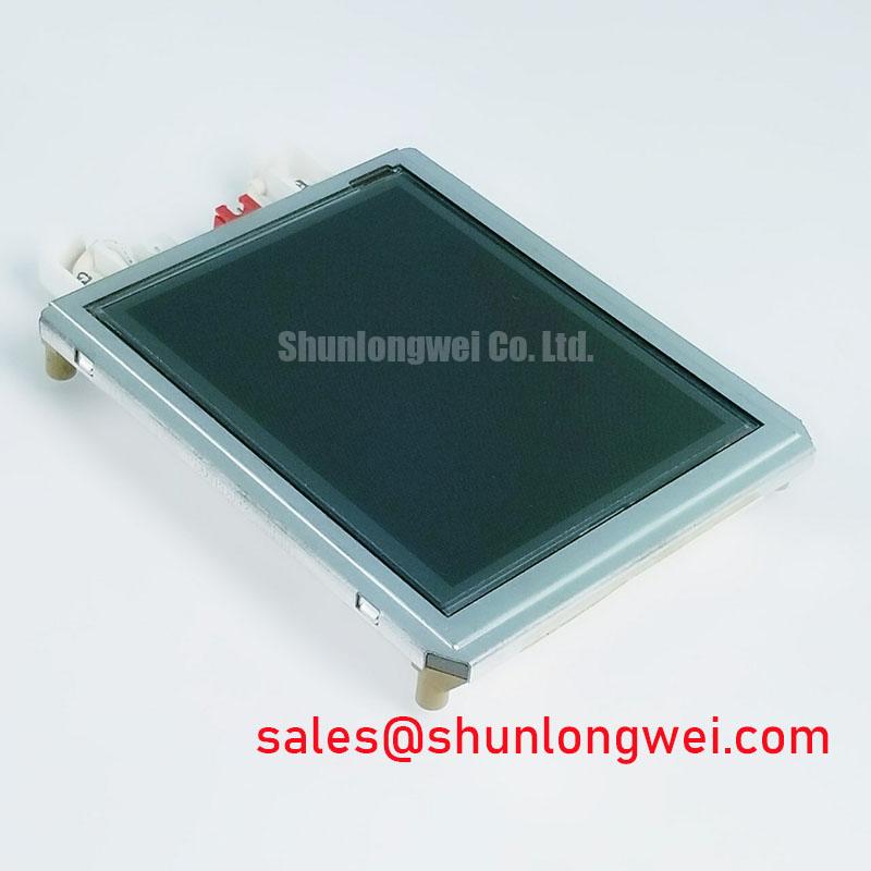
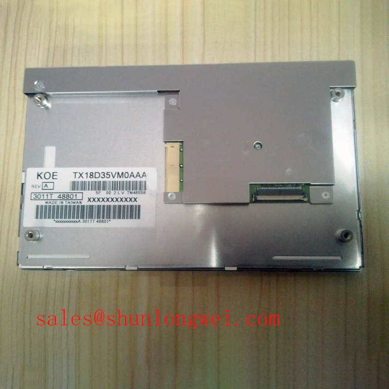
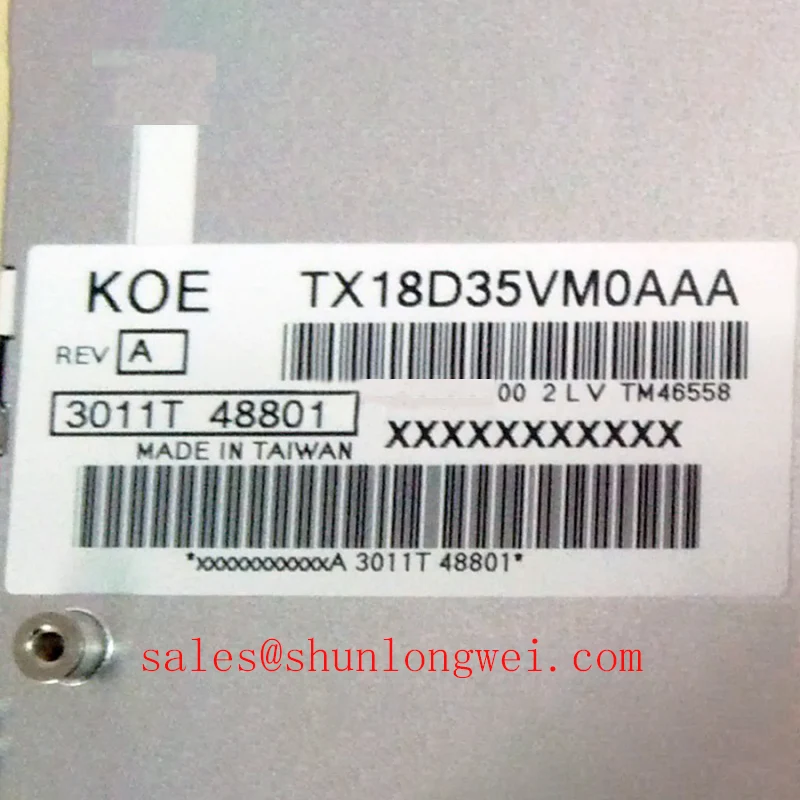
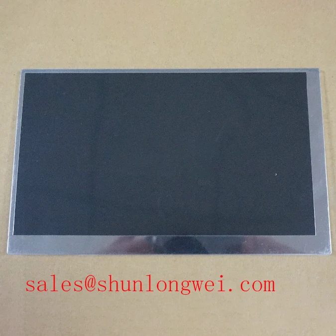
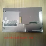
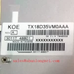
The TX18D35VM0AAA is a KOE / Hitachi TFT LCD display module classified as an Industrial Grade LCD/HMI Panel. Its supplied factory identification confirms a TFT LCD Display Module. Electrical interface, logic supply, backlight type, luminance, resolution, mounting geometry, timing, and environmental limits must be checked against the original panel documentation and the equipment service record before replacement or system integration.
| Item | Confirmed Information |
|---|---|
| Model | TX18D35VM0AAA |
| Manufacturer | KOE / Hitachi |
| Product Category | Industrial Grade LCD/HMI Panel |
| Module Type | TFT LCD Display Module |
For a display replacement in a protection relay cabinet or SCADA dispatch console, begin with the original cable routing rather than assuming that a visible image fault belongs to the panel. A flat flexible cable routed alongside inverter output wiring, contactor coils, switching power supplies, or variable frequency motor circuits can collect common mode interference. Pixel jitter, intermittent horizontal bands, or image disturbance during nearby motor switching should be investigated by comparing the panel connection with a known stable signal path.
Design Consideration: Where the host equipment uses a shielded display cable and a conductive connector shell, shield termination should preserve the enclosure’s intended continuity around the connector. A partial shield connection, loose shell hardware, or an unbonded cable screen can reduce the effectiveness of the cabinet’s noise control arrangement. System engineers should assess bonding continuity, cable strain relief, and the route of the display harness while checking the original equipment electrical documentation.
Common mode ferrites can be evaluated as part of the host system’s cable assembly when conducted or radiated disturbance is observed. Their material selection, placement, and impedance behavior are system dependent and should be confirmed through on equipment testing. A ferrite added without checking signal integrity can alter the behavior of a high speed interface, so the display image should be observed through normal equipment operating states after any harness change.
The supplied factory information does not identify the backlight technology or publish a brightness retention curve for the TX18D35VM0AAA. It would therefore be inaccurate to assign an LED half brightness lifetime, a constant current driver specification, or a stated operating life to this model. During preventive maintenance, record the actual brightness trend of the installed assembly, compare it with an accepted reference display where available, and inspect whether reduced readability tracks panel aging, a backlight supply issue, surface contamination, or enclosure temperature.
For technicians reviewing adjacent stock during a repair assessment, TX20D200VM2BVA can be reviewed as a separate display module. It must not be treated as a direct substitute unless the equipment owner verifies mechanical outline, active area, connector position, interface format, timing, supply requirements, and optical requirements against the original system documentation.
Suppressing Acoustic Capacitor Buzz and EMI Emissions across 200 Hz to 1 kHz PWM Frequencies
A buzzing sound near the display power section should be treated as a cabinet level observation, not as proof of a defect inside the TX18D35VM0AAA. Sound can originate from inductors, transformers, ceramic capacitors, backlight power circuitry, or mechanical vibration transmitted through the bezel and mounting frame. First establish whether the sound changes with screen brightness commands, controller activity, cabinet door position, load state, or ambient temperature. This approach keeps the diagnosis measurable and prevents an unnecessary panel exchange.
The published information provided for this product does not confirm whether this module uses CCFL or LED illumination, its backlight ignition requirement, PWM dimming range, dimming ratio, or protection behavior. Do not apply a generic high voltage backlight test or connect an assumed LED driver to the module. The system integrator should verify the required supply voltage, backlight connection, enable logic, and dimming method from the original panel documentation.
Design Consideration: If the host controller uses pulse width modulation for brightness control, the selected frequency and duty behavior should be checked in the complete display assembly. The objective is to avoid visible flicker during text viewing and to avoid exciting audible vibration in nearby power components. Oscilloscope inspection at the controller output and at the specified backlight interface, together with a visual observation under normal cabinet lighting, provides more useful evidence than judging a single acoustic symptom alone.
Direct ambient light can expose weak contrast, surface contamination, or unsuitable enclosure window materials. No official contrast ratio, anti glare treatment, anti reflection coating, or sunlight readability specification has been supplied for the TX18D35VM0AAA. For consoles located near bright windows or illuminated control rooms, assess the installed display with the actual front window, gasket compression, viewing angle, and ambient illumination rather than assigning an unsupported optical rating to the module.
Industrial touch behavior must also remain separate from the display module identity unless a touchscreen assembly is explicitly documented. Capacitive and resistive touch overlays have different responses to gloves, water, protective films, and grounding conditions. If an operator input issue is present, verify whether the fault belongs to the touch overlay, touch controller, front glass, grounding path, or the LCD image path before replacing the display module.
Aluminum Heat Spreader Sizing and Thermal Interface Placement along Narrow Display Edges
Check the panel seating faces and the enclosure’s thermal path before transferring a replacement module into service. A display frame held under uneven force can develop localized mechanical stress, while an obstructed rear cavity can retain heat around the panel and associated power electronics. Clean the mounting land, remove loose debris from the gasket channel, and make sure the module rests naturally before the fasteners are tightened.
⚠️ Maintenance Note: Inspect cabinet cooling paths and perimeter gaskets during scheduled service because blocked airflow or a displaced seal can increase condensation risk and concentrate mounting stress at the display edge.
Design Consideration: Where an equipment enclosure uses aluminum rails or a conductive rear support as a heat spreading feature, the thermal interface should be continuous with the original mechanical design and should not impose a twisting load on the LCD frame. The appropriate material, thickness, contact pressure, and rail geometry are determined by the cabinet structure and by verified temperature measurements at the installed panel. Avoid adding a heat spreader simply because a display appears warm; first determine whether the heat source is the panel, the backlight supply, a nearby processor, or restricted cabinet ventilation.
The supplied factory data does not state the panel operating temperature range, storage temperature range, internal optical material construction, or a backlight L70 or B50 lifetime target. Claims regarding yellowing resistance or multi year backlight life cannot be attributed to this model without the applicable manufacturer documentation. In environments with temperature cycling, engineers should instead monitor enclosure temperature, gasket condition, drain paths, and signs of condensation on the inside of the display window.
When a display image becomes unstable after warmup, inspect the host interface clock and data path with suitable test equipment. Clock jitter, marginal data hold timing, connector movement, and supply noise can each contribute to corrupted video behavior. The correct acceptance limits must come from the original interface specification rather than a generic LCD rule. Reseating the cable, restoring original strain relief, and comparing with a known good controller output are practical checks before attributing the issue to the panel.
For broader maintenance planning around sealing, thermal management, display interfaces, and cabinet level diagnostics, see Industrial Display & HMI Solutions.
VESA versus JEIDA Data Mapping Alignment and Even/Odd Channel Signal Integrity
Before powering a replacement assembly, identify the exact display interface used by the host controller and compare the original cable, connector keying, pin assignment, and controller documentation. Similar connector formats do not establish electrical compatibility. Incorrect data mapping can present as abnormal colors, split images, unstable picture regions, or a display that powers without rendering usable video. These observations should lead to interface verification rather than an assumption that the LCD is defective.
The supplied factory information does not confirm whether the TX18D35VM0AAA uses LVDS, TTL, another interface type, VESA mapping, JEIDA mapping, a logic supply value, or a specified power on sequence. The system integrator should verify the required supply voltage from the original panel documentation. It is also necessary to confirm the required enable sequence and permitted rise time from the relevant manufacturer data before connecting a replacement panel.
Engineering Recommendation: If the original system documentation identifies a differential display interface, preserve the original paired routing, polarity, shielding, and controlled impedance approach. Differential links are commonly routed as matched pairs to reduce susceptibility to external noise, but exact routing rules and timing margins are determined by the source controller, cable assembly, and specified panel interface. Verify the received signal quality against the known good signal path during switching tests in the complete cabinet.
Even and odd channel artifacts can also result from a connector that is not fully seated, bent contact geometry, a compromised flex cable, or an incompatible transmitter configuration. Inspect the connector under suitable lighting, confirm that the locking feature is fully engaged, and avoid repeatedly reconnecting live display cables. If the image fault persists, compare supply stability, panel enable behavior, clock activity, and data output with the original equipment schematic or service procedure.
For high voltage substation protection and SCADA dispatch console maintenance, the practical decision point is documented compatibility. Confirm the original panel’s mechanical envelope, interface, supply, timing, backlight connection, and optical requirements before using the TX18D35VM0AAA in an equipment repair. This keeps the display replacement process aligned with the host system’s verified design boundaries.