




Content last revised on September 10, 2026
Bench Verification Before Installing LJ089MB2S01
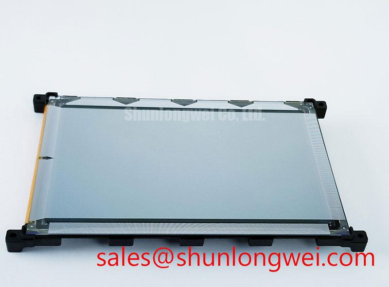
Begin the service inspection by comparing the replacement label with the original panel reference, then check the module for cracked glass, bent connection areas, housing distortion, and contamination before applying power. The product identity supplied for this unit is LJ089MB2S01, manufactured by Sharp, and classified as a Module for LCD display applications.
The available factory information lists the working-voltage category as Standard Industrial Rating and the current field as Standard Operating Current; these labels do not provide numerical voltage or current values in the available product data. The system integrator should therefore verify the required supply voltage, current limit, interface arrangement, and power sequencing from the original panel documentation or the equipment service manual rather than applying a generic LCD value.
For a replacement in a hazardous petrochemical Zone 2 operator station, the display module should be evaluated as one part of the complete protected assembly. The panel, front window, gasket, enclosure, cable glands, and operator-station certification remain system-level matters. This LCD display module must not be represented as independently certified for a hazardous location, explosion protection, EMC compliance, or complete equipment safety.
Cold inspection can include a visual comparison of the active area, connector position, mounting points, flex routing, and bezel contact surfaces. If a previously installed panel showed intermittent lines or localized image loss, record the fault condition before removal. A known-good signal source and a controlled bench supply can help separate display damage from a fault in the host controller, cable, backlight circuit, or enclosure wiring.
Glass Edge and Driver Bond Stress During Service
When an LCD module is removed from an industrial HMI, avoid twisting the glass while releasing clips or mounting hardware. Uneven pressure at the display perimeter can create mechanical stress that is difficult to see during a basic visual inspection. A replacement panel should sit naturally in its frame, with the gasket and retaining hardware distributing force consistently rather than pressing on a single edge or corner.
A practical bench check begins with primary-color images. Display red, green, and blue test fields separately, followed by a white field and a black field. Observe the panel from a normal viewing position and then use a flashlight at approximately 45 degrees to inspect dark shadows, edge marks, and reflections. This method can help distinguish a backlight-related area from a signal-path defect or a line that follows the glass edge. It does not by itself establish the failure mechanism, so suspected defects should be compared with the controller output and a known-good assembly.
Vertical or horizontal lines that remain fixed while the image content changes may justify checking the panel connection, flex routing, and host timing. A dark region that changes with viewing angle may require separate inspection of the backlight, optical stack, or mechanical seating. These observations are diagnostic clues rather than model-specific acceptance limits because the supplied factory data does not define pixel defect criteria, optical uniformity limits, or driver-bond inspection thresholds for LJ089MB2S01.
Low-temperature operation deserves a controlled evaluation when the operator station can experience sub-zero conditions. Liquid crystal response can become slower as temperature falls, and the resulting gray-to-gray behavior may affect moving graphics or rapidly changing alarm screens. Engineers should verify the actual operating temperature range from the original Sharp documentation and assess warm-up behavior inside the completed enclosure. If a heater strip is part of the equipment design, its control should be validated against condensation risk, local hot spots, gasket materials, and the enclosure temperature profile.
⚠️ Maintenance Note: Disconnect power before removing the display cable, and inspect the perimeter gasket and enclosure ventilation path during every scheduled service interval.
Flex Cable Routing and Differential Signal Integrity
Before connecting LJ089MB2S01, document the original cable orientation and connector keying. Do not assume that a similar-looking LCD uses the same pin assignment, logic supply, data mapping, or backlight connection. The available product information does not specify the interface voltage, JEIDA or VESA mapping, differential pair assignment, characteristic impedance, skew allowance, or power-on timing for this model.
When the original panel documentation identifies a differential video interface, route the replacement cable along the same controlled path and keep it away from contactors, ignition sources, switching power stages, and high-current motor conductors. The design objective is to preserve pair symmetry, reduce unnecessary loop area, and avoid sharp bends or unplanned changes in reference-plane geometry. The system engineer should confirm the required differential impedance and skew budget from the host display controller documentation, then validate the result with suitable signal-integrity measurements.
Split-screen artifacts, unstable colors, or intermittent image sections can have several possible sources, including connector contact quality, cable damage, timing incompatibility, supply disturbance, electromagnetic coupling, or incorrect data mapping. Use an oscilloscope at the host-side test point and compare the suspected channel with a known-good signal path. Check the power rail during startup and during the highest display activity rather than measuring only an unloaded static value.
Power-on behavior should be evaluated as a sequence. Confirm that the host controller, display logic supply, reset behavior, video data, and backlight enable follow the timing required by the original documentation. Since no numerical rise-time or supply specification has been supplied for LJ089MB2S01, values such as 3.3 V, 5.0 V, or a particular startup interval must not be assumed. The integrator should verify these requirements from the original panel documentation before connecting the module to a replacement controller.
In a factory environment, the display cable may share an enclosure with variable-frequency drives, relay banks, solenoids, or long sensor lines. Shield termination, bonding, cable separation, and enclosure grounding should be reviewed at system level. A discrete display module cannot independently claim compliance with CISPR, EN 55011, or another complete-equipment EMC standard. Final verification belongs to the assembled operator station under its intended wiring and operating conditions.
For a Zone 2 installation, the display assembly must also be assessed against the certification architecture of the operator station. The enclosure, barriers, cable entries, temperature classification, and service procedures may determine whether the completed equipment remains compliant. The Sharp display product identity and module classification do not replace that system evaluation.
Thermal Uniformity, Optical Aging, and Gasket Stability
Thermal inspection should begin with the complete mounting arrangement rather than the LCD alone. Narrow display edges, nearby power supplies, heater elements, sunlight through an observation window, and restricted airflow can create temperature differences across the panel. An aluminum spreader or mechanical thermal path may be considered where the enclosure design produces a localized hot area, but its size, contact method, electrical isolation, and effect on bezel pressure must be determined by the system engineer.
Do not attach a heat spreader directly to an unverified optical or electrical surface. First identify the approved contact regions from the panel documentation and check that the proposed structure does not obstruct the backlight, flex cable, venting path, or gasket compression. Thermal measurements should be taken at several points during startup, maximum brightness, continuous alarm display, and enclosure heat soak. The purpose is to identify gradients and transient behavior, not to apply an assumed temperature limit that is absent from the supplied factory data.
Brightness control should also be checked at the equipment level. If the host uses PWM dimming, verify the controller’s specified frequency, duty-cycle behavior, startup state, and interaction with the backlight driver. The available information for LJ089MB2S01 does not state a PWM frequency, LED lifetime value, L70 rating, B50 value, optical material specification, or guaranteed sunlight contrast ratio. Those figures should be taken only from the applicable Sharp technical documentation or the original equipment specification.
Direct sunlight can reduce apparent contrast even when the LCD is operating correctly. For an operator station installed behind a viewing window, evaluate the complete optical path, including the front cover, reflections, ambient illumination, anti-glare treatment, and viewing angle. The Sharp Display Solutions Official Portal provides the appropriate manufacturer context for confirming display technology and application documentation.
Thermal cycling can also affect adhesive layers, perimeter sealing, and gasket compression. Inspect for lifting edges, moisture traces, pressure marks, and changes in frame fit after environmental testing. The available product data does not provide a guaranteed cycle count, sealant construction, polarizer adhesive rating, condensation performance, or operating range for this model. Any qualification from low temperature to elevated temperature should therefore use the original Sharp specification and the limits of the completed operator station.
For broader enclosure, sealing, cable routing, and industrial HMI integration considerations, engineers can consult the Industrial Display & HMI Solutions engineering guide. When the module is considered for a petrochemical monitoring terminal or explosion-protected operator console, the final review should confirm mechanical fit, electrical compatibility, thermal behavior, optical readability, gasket integrity, and the certification requirements of the complete assembly.



