


Content last revised on September 12, 2026
Industrial EMI Noise Immunity, Chassis Shielding Continuity and Common-Mode Ferrite Chokes
When a replacement display is installed near variable-frequency motor drives, begin with cable routing and bonding rather than immediately changing display settings. Inspect the display cable for crushed sections, incomplete connector engagement, and shield termination that has been interrupted by paint, loose hardware, or an uneven chassis contact. The display module itself cannot independently claim compliance with an entire machine’s EMC requirements; system-level results depend on the host controller, cable construction, enclosure, grounding arrangement, drive switching behavior, and installation workmanship.
A Design Consideration for a noisy control cabinet is to preserve a continuous shield path between the display assembly and the controller wherever the original design requires it. A 360-degree shield termination can reduce the area available for common-mode current to couple into high-speed display conductors, but the correct termination method remains dependent on the connector and cable construction. Engineers should confirm whether the original assembly uses LVDS, TTL, or another display interface before selecting a replacement cable or adding a common-mode ferrite choke. The supplied factory information does not specify the electrical interface for this model.
Pixel jitter, intermittent horizontal bands, or unstable image content should be investigated as system symptoms rather than assigned to one cause. Compare the display clock and data behavior with a known-good signal path, inspect the reference ground under operating load, and observe whether the fault changes when the motor drive changes speed. If a ferrite component is considered, its impedance characteristics, current capability, placement, and effect on signal integrity should be validated with the actual cable and transmitter. Adding suppression without checking the display timing can create a new signal-quality problem.
Clock jitter tolerance, setup time, and hold time are properties of the complete transmitter, receiver, cable, and operating-temperature combination. They should be checked against the original display interface specification and the controller timing documentation. Do not infer TTL or LVDS timing limits from the NEC model number alone. For background on display architectures, signal paths, and common integration faults, engineers can consult The Ultimate Guide to Industrial TFT-LCD Technology.
In a Zone 2 operator station, the enclosure designer must separately verify hazardous-area construction, cable glands, bonding, heat dissipation, and certification of the complete equipment. The LCD module should be treated as one part of that assessment, not as an independent explosion-proof or EMC-certified assembly.
Optical Luminance Degradation and Backlight Modernization Retrofit Pathways
Before planning a backlight retrofit, document the original display’s backlight connector, inverter or driver arrangement, enable signal, dimming method, and power sequence. The supplied factory parameters identify the product as a TFT-LCD display module but do not confirm whether this specific unit uses CCFL, LED, or a particular driver topology. A replacement backlight must not be selected from appearance alone.
For an existing CCFL-based assembly, cold ignition behavior, inverter output, insulation spacing, and lamp current are system-specific design matters. High-voltage ignition values should only be used when they are stated in the original service documentation or measured using equipment rated for the circuit. The display module’s product identification does not, by itself, authorize a particular inverter setting. Technicians should isolate the backlight circuit, follow the equipment lockout procedure, and verify that residual energy has been discharged before handling connectors.
An LED modernization path may reduce dependence on an aging inverter, but it introduces its own requirements. The proposed LED driver must match the replacement light source, current regulation method, enable logic, dimming control, thermal behavior, and mechanical light distribution. A constant-current driver can be considered only after the optical and electrical characteristics of the actual replacement assembly have been verified. PWM dimming performance, including any proposed high dimming ratio, should be validated on the complete panel because visible flicker, control noise, or uneven brightness can result from an unsuitable driver frequency or control waveform.
Do not publish a fixed brightness half-life or MTBF value for this model without a manufacturer specification or an identifiable reliability report. Luminance aging depends on the backlight source, drive current, temperature, duty cycle, optical stack, and enclosure conditions. A maintenance team can establish a useful baseline by recording uniformity and brightness at commissioning, then repeating the measurement under comparable settings. Any deterioration trend should be compared with the equipment’s functional alarm and readability requirements.
Direct sunlight, viewing direction, protective windows, anti-glare treatment, and enclosure reflections all affect perceived contrast. The available factory information does not confirm a contrast ratio, anti-glare surface, sunlight readability rating, or optical bonding construction for the NEC NL6448BC33-71C. If the display is being considered for a petrochemical field terminal, the integrator should evaluate the complete front assembly under the actual lighting condition rather than relying on a generic TFT-LCD rating.
Where the host equipment uses a related NEC display topology, engineers may also review NL10276BC30-24D as a separate reference product. It should not be assumed to share the same electrical or mechanical characteristics as the NL6448BC33-71C without documentation.
Chassis Fastener Loading and Optical Mura Prevention
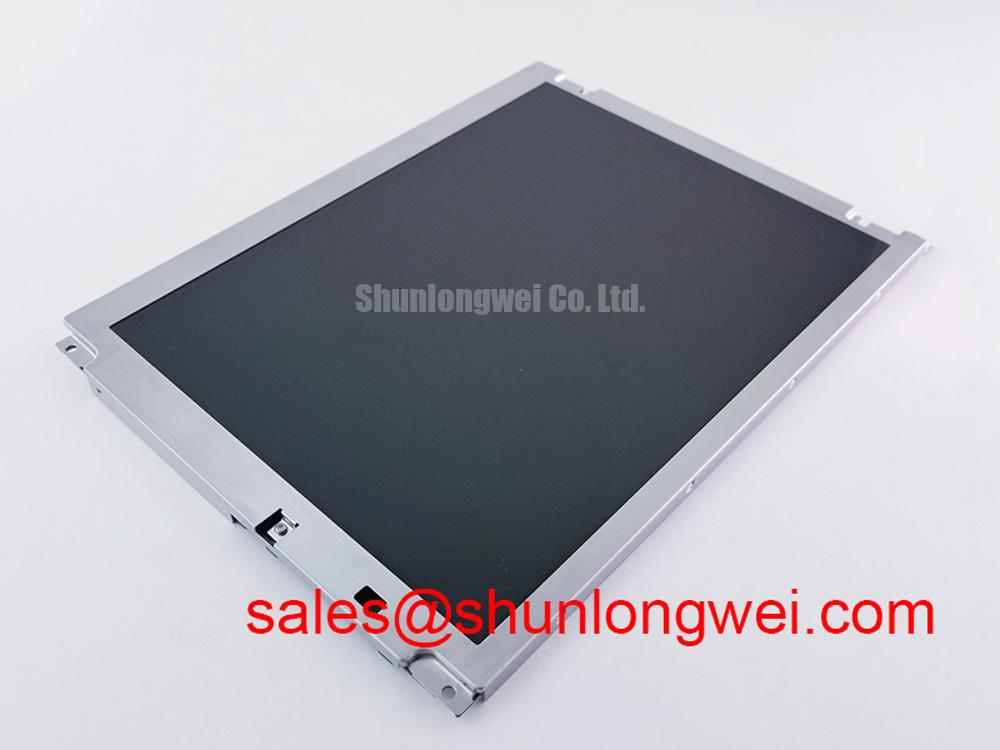
During installation, place the module on a clean, level support surface and inspect the bezel, mounting tabs, gasket contact area, and cabinet opening before tightening hardware. Uneven chassis loading can transmit stress into the display assembly and create localized optical non-uniformity, especially when the panel is clamped against a distorted bezel or compressed gasket. The manufacturer’s supplied data does not provide an outer bezel envelope, mounting-hole drawing, screw size, or approved fastening torque for this model.
Any proposed M3 fastener torque must therefore be treated as a Design Consideration, not an official NEC specification. The correct value is determined by the cabinet material, thread engagement, fastener condition, gasket compression, mounting bracket stiffness, and the display manufacturer’s mechanical drawing. Use the original service documentation where available, tighten progressively across the mounting points, and check that the bezel remains free from twist. The purpose is to distribute mechanical load while maintaining the required dust and moisture interface; it is not to force the module into alignment.
After mounting, inspect the display with a uniform test image at several brightness levels. Look for corner darkening, pressure marks, bands, or changes that appear only after the cabinet screws are tightened. If the image changes when the bezel is relieved, investigate the mechanical interface, bracket flatness, gasket position, and cable strain before replacing electronic parts. A visible artifact can have several interacting causes, including optical contamination, signal behavior, backlight non-uniformity, and mechanical stress.
FPC and flexible display cables require a controlled bend path and strain relief that follows the original equipment design. Avoid folding directly at the connector, pulling the cable while the latch is open, or allowing a cover to press against the flex. The correct bend radius and insertion method should be obtained from the applicable cable and connector documentation. A connector that appears seated may still have an incompletely locked actuator, so inspect the latch position and verify image stability during a controlled vibration check.
Maintenance Note: Inspect the cabinet ventilation path and gasket seating during scheduled service, because dust accumulation and uneven sealing can increase thermal stress and compromise the display opening.
For a same-family replacement evaluation, NL10276BC16-06 may be reviewed as a separate compatible-device reference. Compatibility must be confirmed through dimensions, connector definition, timing, backlight requirements, and the original equipment documentation; the link is not a substitute for a formal interchangeability check.
Grayscale Behavior and Viewing Direction Alignment
Set the display at the operator’s normal eye position before judging grayscale quality, shadow detail, or apparent contrast. TFT viewing behavior changes with vertical and horizontal angle, so a panel that looks correct during bench inspection may show tonal inversion or reduced legibility when installed above, below, or to one side of the normal operator position. The supplied information does not confirm whether the NL6448BC33-71C uses a normally white TN cell, IPS, MVA, or another panel mode, and it does not state a viewing-angle specification.
Panel mode, grayscale inversion, contrast, and viewing direction must be verified from the original NEC datasheet or a controlled sample inspection. If grayscale steps change noticeably as the operator moves vertically, adjust the display mounting angle only if the cabinet design permits it. Do not compensate for a viewing-angle limitation by arbitrarily changing gamma or brightness, since that can hide important process indications and reduce daylight readability.
Surface treatment also requires practical evaluation. An anti-glare layer may reduce reflected overhead lighting, but it can alter perceived sharpness, haze, and contrast through a protective window. The correct result depends on the panel surface, cover material, ambient illumination, and operator distance. Since no anti-glare specification is supplied for this model, the integrator should verify the front-surface construction before ordering a bonded cover or applying an aftermarket film.
Long-term static HMI screens should be managed through the host application where process requirements allow it. Rotating fixed graphics, reducing unnecessary maximum brightness, and using an approved screen saver may reduce persistent image retention risk, but these are system operating practices rather than guaranteed properties of the display module. Any suspected residual image should be checked with neutral and uniform test patterns after the panel has returned to a controlled operating condition.
Power sequencing is equally important during service. Confirm the original controller’s supply order, display enable behavior, reset logic, and discharge path before connecting the replacement. A white screen, delayed image, or residual image after shutdown may involve timing, missing control signals, incorrect cable orientation, or a backlight condition. Verify each signal against the equipment schematic and a known-good unit rather than assigning the symptom to a single internal failure.
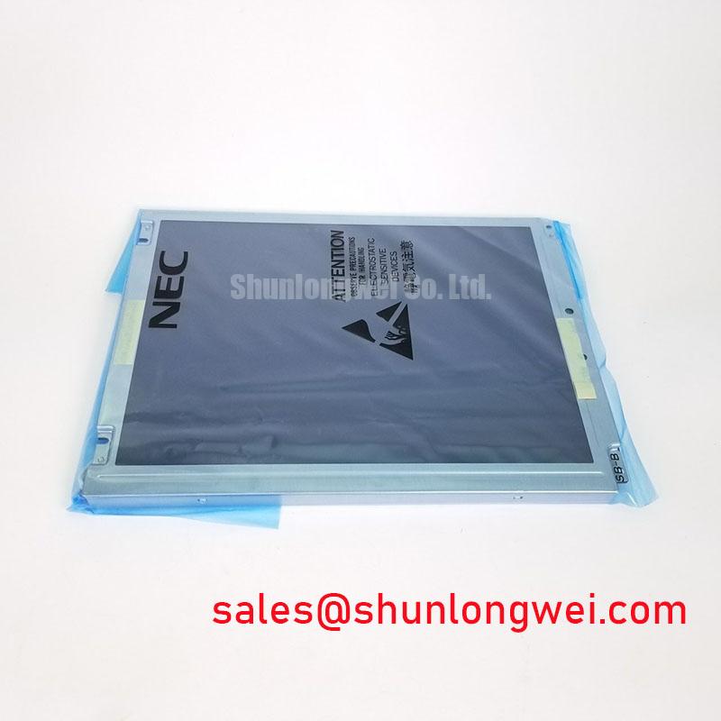
Cold-start testing should be performed with the display installed in its actual mechanical environment. Observe startup response, image stability, condensation risk, and cable flexibility after the enclosure reaches the intended temperature. The NEC NL6448BC33-71C is identified here as an industrial-grade TFT-LCD display module, but no operating-temperature range, condensation rating, sealing level, or response-time specification has been supplied. Those limits must be confirmed from the applicable factory documentation before deployment.

