
Content last revised on November 6, 2026
Contrast, Viewing Angle & Ambient Lighting Checks
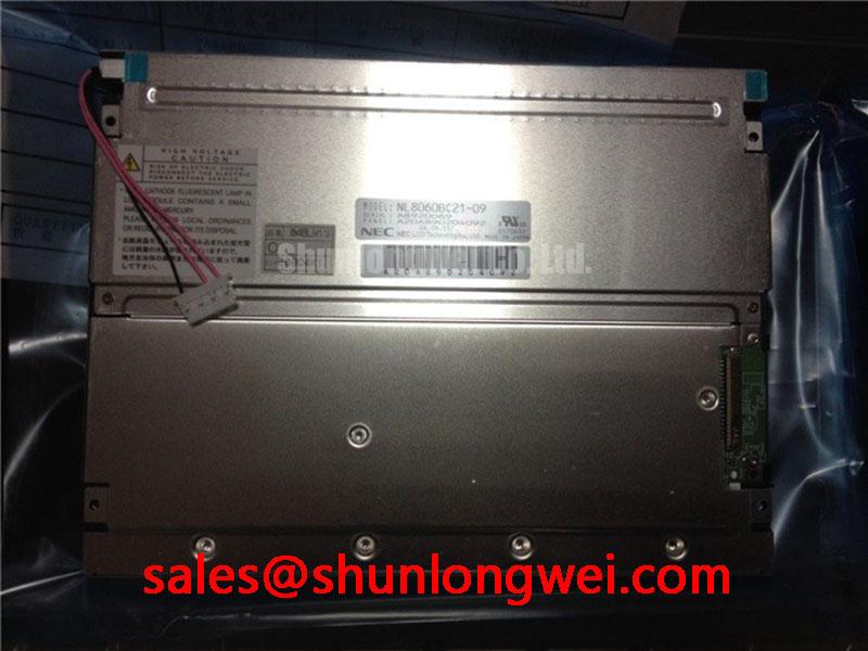
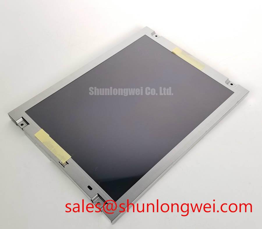
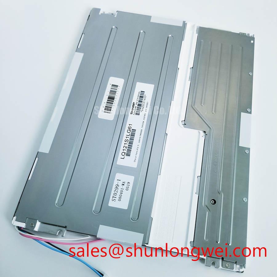
For a blank or unstable operator terminal, first confirm the panel label and compare the host controller’s signal format and connector pinout before applying power. The supplied product data identifies Manufacturer: NEC, Part Number: NL8060BC21-11KG, and Resolution: 800 x 600. It describes a TFT-LCD active-matrix color display module, but the listed diagonal size and “LVDS / TTL” interface description require verification against model-specific documentation. No numeric luminance, supply voltage, timing limits, or dimensional drawing is specified here. Treat those values as items to verify against the panel documentation and the equipment’s original configuration before installation.
When a display appears washed out or its grayscale changes across the viewing area, compare the image at the installed viewing angle and under the actual ambient lighting. Viewing-angle behavior, contrast, and grayscale response are panel-specific; the supplied specifications do not establish a TN, IPS, or MVA mode, a viewing cone, or an anti-glare surface treatment for this part. Do not infer those features from the resolution or model number.
In a machine-tool HMI, inspect the panel surface under both operating illumination and a diffuse inspection light. Glare from a task lamp or enclosure window can reduce perceived contrast without indicating an electronic fault. If dimming is controlled by the host, check the controller’s documented dimming method and observe the screen for flicker or instability across its operating range. PWM frequency and duty-cycle behavior are system-level settings, not confirmed specifications for this panel.
NEC’s website is a starting point when checking manufacturer resources; obtain model-specific documentation before making installation decisions. For an alternative evaluation, NL6448BC26-27F is a separate model; do not assume equal resolution, dimensions, connector assignment, or optical performance without comparing its documentation with the host requirements.
Display Interface Synchronization & Logic Power Rail Verification
Resolve the interface question before connecting the replacement: the “LVDS / TTL” description in the supplied product data does not establish that this panel supports both interfaces, nor does it define a connector pinout, signal mapping, or logic voltage. Compare the equipment schematic, panel connector drawing, and controller output specification. Confirm the required power rail and startup sequence from the applicable documentation rather than selecting a voltage by assumption.
For an LVDS host, verify lane assignment, clock polarity, and pixel-data mapping. For a TTL host, check the RGB bit width and synchronization signals. A host and panel using different interface types require an appropriate interface converter; they cannot be connected directly. JEIDA and VESA mapping are not interchangeable assumptions for an LVDS link; confirm the configured format at both ends. If the image is split, offset, or unstable, inspect cable seating and compare clock and data behavior with a known-good signal path. Minimize avoidable routing discontinuities and keep clock and data paths organized as a design consideration, with final signal integrity assessed in the assembled equipment.
Use the panel’s specified backlight drive arrangement and the host’s documented protection and fault reporting. The supplied data does not identify the backlight technology, driver topology, or an MTBF value, so do not apply a generic LED lifetime figure to this model. For a related NEC display option in a different system design, see NL10276BC20-18D; it is not evidence of electrical or mechanical interchangeability.
| Evaluation item | NL8060BC21-11KG | NL6448BC26-27F |
|---|---|---|
| Manufacturer | NEC | Verify product documentation |
| Resolution | 800 x 600 | Verify product documentation |
| Interface and pinout | Verify interface type and connector details against model-specific documentation | Verify product documentation |
| Mechanical fit and optical characteristics | Confirm against the panel drawing and equipment opening | Confirm against the panel drawing and equipment opening |
💡 Pro Tip: Before ordering or fitting a candidate panel, compare its connector pinout and active-area dimensions with the original assembly drawing, not just the model name or resolution.
Full-Screen Primary Color AOI Screening: Stuck Sub-Pixels & Background Uniformity Audit
Screen the panel with solid red, green, blue, white, and black images from the intended controller. Look for persistent pixel defects, uneven illumination, color imbalance, and line artifacts, recording whether each symptom remains fixed as the displayed content changes. This helps distinguish repeatable image artifacts, though additional checks may be needed to isolate the panel, cable, or controller.
If a region looks dark, view it under controlled ambient light and compare the appearance with the backlight operating. An angled inspection light can help distinguish surface reflections from changes in emitted image, but it cannot by itself identify a specific internal failure. Avoid attributing a line defect to a particular internal bond or driver structure without diagnostic evidence.
For timing-related artifacts, review the host’s pixel clock and data setup/hold requirements against the panel documentation. Observe the signal path at the controller and panel connector using suitable probing practice; measurement loading and grounding can affect high-speed signals. An AOI record should include the test pattern, viewing conditions, and the equipment configuration so that a later comparison is meaningful.
Operating-Temperature Verification & Low-Temperature Display Behavior
The supplied product data does not specify an operating-temperature range for NL8060BC21-11KG. For equipment exposed to cold starts or thermal cycling, establish the permitted panel and backlight conditions from the applicable manufacturer documentation, then assess the complete enclosure and host system over their intended environment.
At low temperature, display response and visual uniformity can change; at elevated temperature, the panel and its surrounding components may experience different operating conditions. Record image behavior after the assembly reaches its normal operating state, and compare it with the equipment’s acceptance criteria. Avoid using a generic Gray-to-Gray response or seal-material claim as a substitute for model-specific data.
Mechanical compatibility also requires more than matching the nominal diagonal and resolution. Check active-area position, overall outline, mounting points, connector orientation, cable bend path, and enclosure opening against the original drawing. For signal routing in electrically noisy machinery, maintain orderly differential-pair routing where applicable and validate the assembled link under representative operating conditions. Industrial display Application Guide provides broader HMI integration context.