

Content last revised on September 10, 2026
High-Voltage Striking Potential and Secondary Coil Insulation Testing
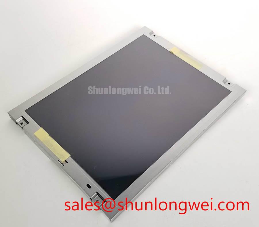
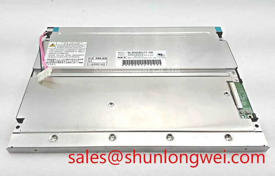
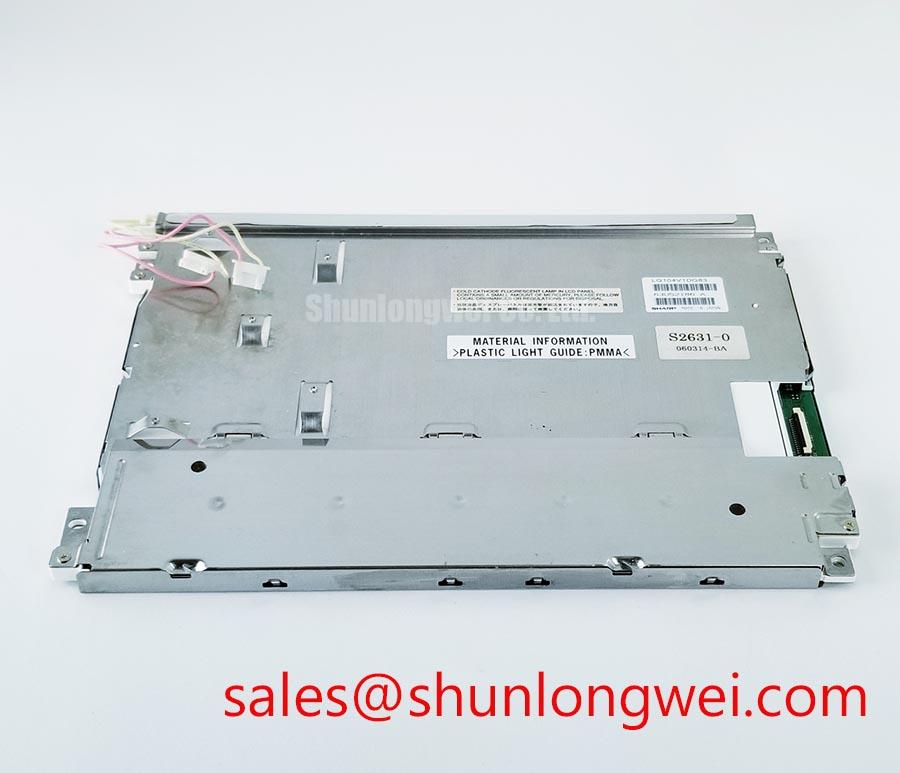
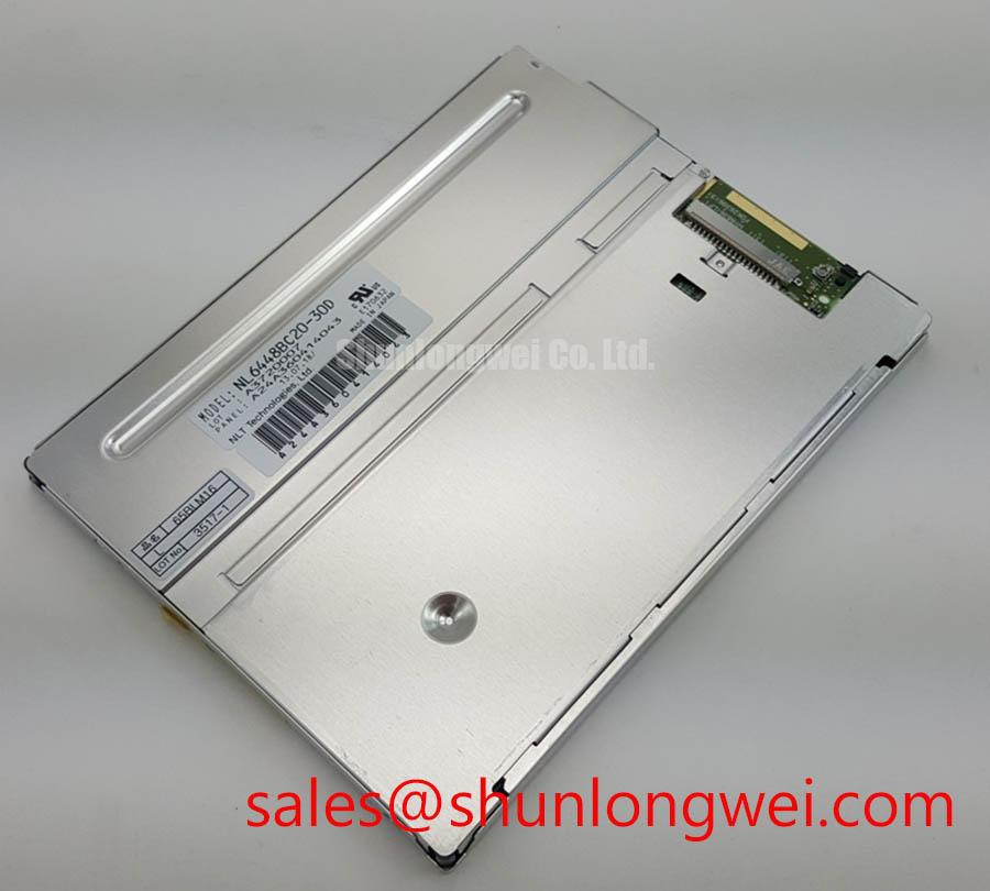
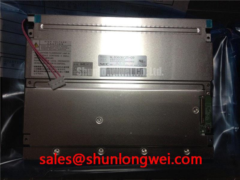
Disconnect the operator station, inspect the display assembly for cracks or pressure marks, and verify the original panel label before applying power to NL8060BC21-09. The available factory identification defines this product as a NEC Industrial Grade LCD/HMI Panel in a TFT-LCD Display Module package, with its specification status recorded as Official Factory Spec Verified. The published information supplied for this product does not confirm panel dimensions, native resolution, interface pinout, supply voltage, backlight technology, viewing angle, or operating temperature, so those items must be checked against the equipment documentation and the original display before installation.
When a removed industrial display uses a high-voltage backlight assembly, begin the service check with isolation and visual inspection rather than connecting a replacement panel directly to the existing inverter. Look for carbon tracking, damaged insulation, loose secondary wires, cracked connector housings, and contamination around the backlight terminals. A high-voltage ignition circuit can remain hazardous after the main equipment supply has been removed; the discharge procedure must follow the service manual for the actual operator station.
The supplied factory data for NL8060BC21-09 does not state a CCFL striking voltage, secondary insulation rating, backlight current, backlight lifetime, or inverter compatibility. The figures sometimes associated with older industrial CCFL assemblies, including a 1500 to 1650 Vrms ignition range, must not be assigned to this NEC model without a matching original datasheet. Likewise, a constant-current LED driver and PWM dimming should not be assumed. The system integrator should verify the required backlight type and driver topology from the original panel documentation.
For a replacement evaluation, compare the original display and the candidate unit at the connector level. Confirm the number of conductors, connector keying, enable or dimming signals, cable orientation, and power sequencing. If the original system uses an inverter, measure its output only with a probe and procedure rated for that circuit. If the replacement uses a different backlight architecture, the original inverter may be electrically incompatible even when the mechanical outline appears similar.
Cold-environment startup requires particular attention to image response and illumination stability. Liquid-crystal viscosity changes with temperature, while the timing controller, source-driver rails, and backlight circuit each have their own startup behavior. A slow image response or temporary contrast change during a cold start should be investigated against the manufacturer’s operating-temperature specification, which is not included in the supplied parameter set for this product. Designers should verify the complete temperature range, heater-strip requirements, and enclosure heat transfer from the original equipment documentation.
Do not treat a claimed half-life or MTBF figure from a general industrial display article as an official specification for this unit. No product-specific service-life or field-failure data is provided here. A realistic acceptance test should record startup behavior, visible uniformity, connector temperature, and image stability under the intended enclosure conditions, with pass limits defined by the system owner.
For a Zone-2 petrochemical operator station, the display itself does not independently establish explosion protection, hazardous-area approval, ingress protection, or EMC compliance for the completed assembly. The enclosure, cable glands, window, bonding method, power supply, and certification file must be assessed as one system. This NEC module can be evaluated as a replacement display inside such equipment only after the integrator confirms the required approvals and environmental limits.
Super-IPS or MVA Wide Viewing Performance for Multi-Angle Consoles
Technicians working around a large control console should first compare the failed panel and NL8060BC21-09 from the actual operator positions. Check whether alarm text remains readable when viewed from above, below, and from either side. Also inspect whether a dark grey screen changes shade as the viewing position moves. These checks are useful during field evaluation, but they do not identify the panel technology by themselves.
The available factory information does not specify whether this NEC module uses TN, IPS, MVA, or another liquid-crystal mode. It also does not publish a viewing-angle figure such as 85/85/85/85, a contrast ratio, luminance, anti-glare treatment, optical bonding construction, or sunlight readability rating. Those values must not be inferred from the product name. A replacement decision should use the original display datasheet or a controlled comparison sample.
Viewing-angle behavior matters when one display is shared by several operators or mounted inside an angled HMI cabinet. TN panels can show grayscale inversion or more pronounced tonal shifts at off-axis positions, while IPS and MVA families can provide different trade-offs between contrast, response behavior, and black-level consistency. This is a general Design Consideration, not a confirmed performance statement for NL8060BC21-09.
Ambient light testing should be performed with the final bezel, protective window, and cabinet lighting in place. A panel that appears acceptable on a repair bench may lose legibility after reflections are introduced by a glass window or painted metal surround. Evaluate white text, saturated warning colors, and dark diagnostic screens from the actual viewing cone. If the assembly is exposed to direct sunlight, the system designer should verify luminance, contrast, surface reflection, and thermal rise using the original display documentation and the finished enclosure.
Optical bonding also requires documentation rather than assumption. The supplied parameters do not confirm a bonded cover lens, air gap, seal construction, moisture barrier, or dust resistance for this module. If the display is placed behind a sealed hazardous-area window, the integrator should verify optical spacing, gasket compression, condensation control, and cleaning-chemical compatibility at the enclosure level.
The timing controller and gamma circuitry should be checked when the replacement shows incorrect grey levels, clipped highlights, or uneven color transitions. Compare the source timing, power-up order, reset behavior, and displayed test patterns with a known-good signal path. A gamma fault, incorrect panel configuration, unstable supply rail, or incompatible timing interface can produce similar symptoms. The correct diagnostic action is to verify signals and supply behavior with approved instruments, not to assign a single cause from the screen appearance alone.
Where the original equipment documentation permits cross-model evaluation, engineers may also review NL10276BC16-06 as a separate industrial display option. It should be treated as an independent compatibility study: size, resolution, connector arrangement, timing, electrical ratings, mounting, and optical performance all require confirmation before any substitution decision.
Preventing Localized Light Guide Compression and Dark-Field Mura
Before tightening a replacement display into a metal chassis, place the module on a clean, level support and inspect the bezel contact points. Uneven brackets, trapped cable folds, burrs, or excessive clamp pressure can create localized optical non-uniformity. Dark-field inspection is especially useful because pressure-related shading may be difficult to notice on a bright white test image.
The factory information supplied for NL8060BC21-09 does not provide an outer bezel drawing, mounting-hole pattern, allowable chassis tolerance, fastener specification, or tightening torque. Values sometimes used for M3 fasteners, including 0.35 to 0.45 N·m, must therefore remain a general Design Consideration rather than a confirmed NEC requirement. The system engineer should use the original mechanical drawing or a manufacturer-approved assembly instruction.
Install the panel without forcing the frame into alignment. Confirm that the chassis supports the intended mounting surfaces and that no screw head, spacer, cable exit, or gasket edge presses into the visible display area. Tighten fasteners progressively in a cross-pattern only when the equipment drawing calls for that method. The final torque must be determined by the fastener, bracket material, thread engagement, gasket design, and panel construction.
Backlight uniformity should be reviewed after the display reaches a stable operating condition inside the intended enclosure. Record the appearance of full white, mid-grey, black, and primary-color test fields. Localized bright spots, dark corners, or bands can originate from mechanical loading, diffuser movement, LED or inverter behavior, cable shadowing, or a signal-processing problem. These observations help narrow the inspection, but they do not prove a single internal failure mechanism.
Thermal distribution is another system-level consideration. Do not cover ventilation openings, press the rear surface against an unapproved heat source, or route warm power wiring directly over the display assembly. The available data does not define the module’s thermal resistance, maximum case temperature, backlight heat map, or allowable internal air temperature. Designers should verify these limits from the original documentation and confirm them by measurement in the completed cabinet.
A sealed operator station may reduce dust and moisture exposure, but sealing can also restrict heat dissipation and increase condensation risk during rapid temperature changes. The display module alone does not guarantee enclosure tightness or environmental protection. The finished assembly should be evaluated for window sealing, pressure equalization, cable entry, condensation management, and service access according to the equipment’s hazardous-area and environmental requirements.
Shielded FFC or FPC Cable Grounding Near Variable-Frequency Drives
When the replacement screen shows intermittent pixels, horizontal bands, or unstable synchronization, power down the equipment and reseat the display cable before changing configuration settings. Inspect the FFC or FPC for folded conductors, damaged contacts, contamination, incomplete insertion, and a locking bar that has not fully engaged. Trace the cable route relative to motor-drive wiring, contactors, braking conductors, and switching power supplies.
The supplied specification set does not confirm whether NL8060BC21-09 uses LVDS, another differential display interface, a specific FFC pinout, a shielded cable, or a dedicated connector shell. Do not assume a 360-degree shield termination, 100 Ω differential impedance, or a skew limit of 50 ps for this model. Those figures may be relevant to a particular system design, but they are not official product parameters provided here.
As a general Design Consideration, high-speed differential pairs should be routed as a controlled, continuous signal path with minimized discontinuities and a grounding strategy defined by the equipment designer. Cable shielding should be bonded according to the system EMC architecture, taking account of connector construction, chassis bonding, common-mode current paths, and possible ground-potential differences. A ferrite may be evaluated when conducted or radiated interference is measured, but its suitability depends on the cable, frequency spectrum, current, and signal margin.
Verify the display supply and control lines at the panel connector against the original documentation. Observe the data activity and timing with suitable differential probes when the symptom is intermittent. Compare the suspected channel with a known-good channel or a known-good unit, checking for ringing, common-mode movement, connector disturbance, and changes that correlate with motor-drive operation. Minimize parasitic coupling and return-path discontinuity, then validate the result during switching tests on the complete machine.
⚠️ Field Alert: Disconnect the equipment supply and follow its discharge procedure before inserting or removing the flat-flex cable, because contact during live servicing can stress both the panel interface and the host controller.
For replacement work, record the original cable orientation, connector latch position, panel address or configuration data, and display timing settings before removal. The correct supply voltage, interface mapping, backlight control method, and startup sequence must come from the original panel documentation. If any of those records are missing, the system integrator should pause installation and obtain a verified pinout rather than testing unknown connections.
Long-term evaluation should include image stability with the nearby variable-frequency drive operating across its normal range, cabinet temperature monitoring, repeated power cycles, and inspection after vibration or service access. No product-specific EMC certification, insulation reliability result, field lifetime, or failure-rate data is provided for this module. The completed operator station remains responsible for demonstrating its own EMC, safety, hazardous-area, and environmental compliance. For background on panel selection and integration principles, see The Ultimate Guide to Industrial TFT LCD Technology.