

Content last revised on September 22, 2026
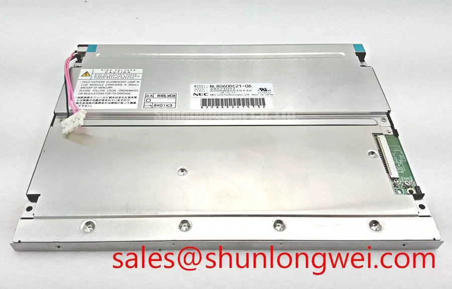
NEC NL8060BC21-06 Identification Before Installation
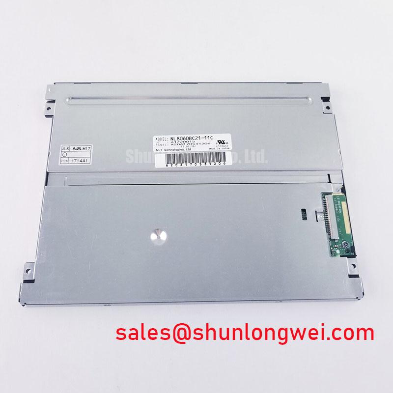
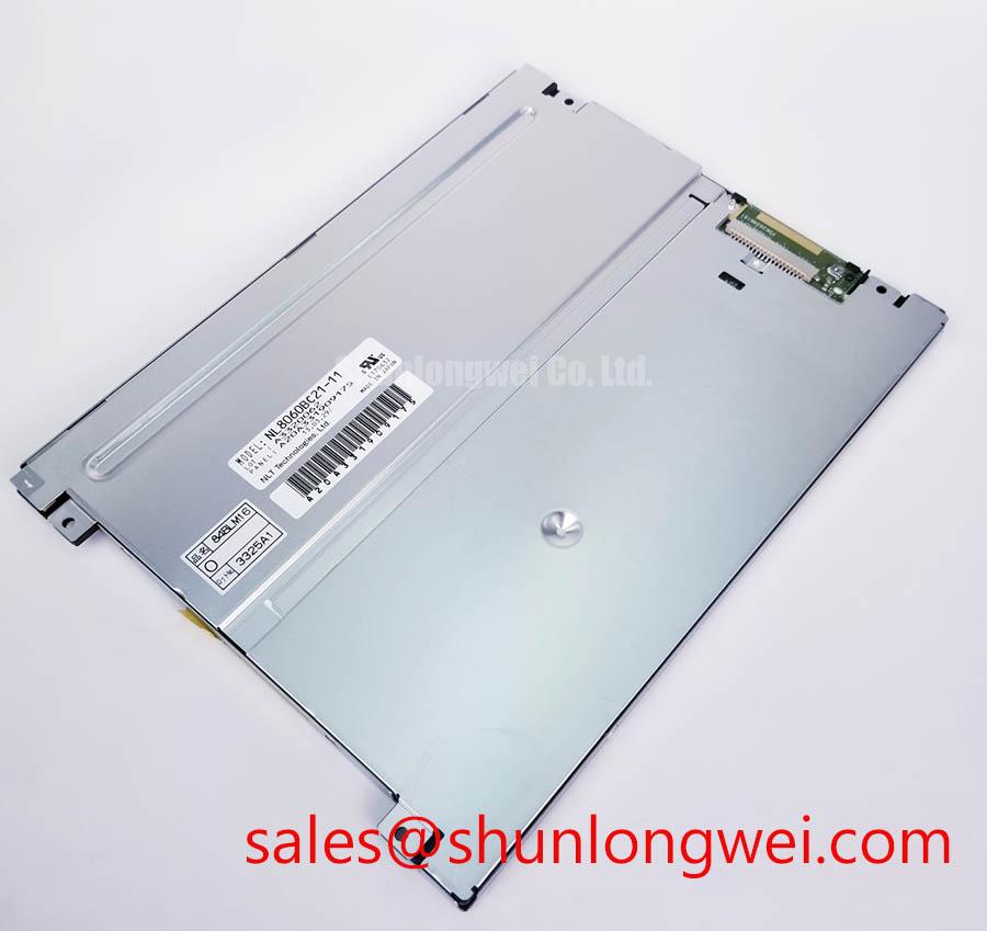
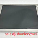
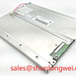
Begin the service inspection by comparing the panel marking, connector arrangement, mechanical cutout, and display image against the removed unit before applying power. The NL8060BC21-06 is identified in the available product information as an NEC Industrial Grade LCD/HMI Panel in a TFT-LCD Display Module format.
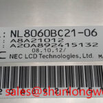
For a replacement evaluation, the product identity should be confirmed at three levels. First, verify that the marking reads NL8060BC21-06 and that the manufacturer is NEC. Second, compare the panel’s external dimensions, mounting points, connector position, cable orientation, and optical window with the equipment documentation. Third, confirm the host system’s interface and power requirements from the original panel documentation. The available product data does not establish a complete electrical pinout, supply voltage, backlight architecture, luminance value, viewing angle, contrast ratio, response time, or operating temperature range, so these values should not be inferred from the model number.
| Model | NL8060BC21-06 |
| Manufacturer | NEC |
| Product category | Industrial Grade LCD/HMI Panel |
| Construction classification | TFT-LCD Display Module |
In heavy mining shovel and earthmoving equipment telematics displays, the panel should be assessed as part of the complete display assembly rather than as an isolated image source. Enclosure sealing, shock transmission, cable restraint, heat flow, controller compatibility, and the condition of the front gasket can all influence field performance. These are system-level design considerations, not additional factory specifications for this NEC module.
Where a same-class replacement comparison is required, engineers may review NL10276BC16-06 as a separate product reference. Electrical, optical, and mechanical interchangeability must be verified from the original equipment documentation before any substitution is considered.
Full-Screen Primary Color AOI Screening: Stuck Sub-Pixels and Background Uniformity Audit
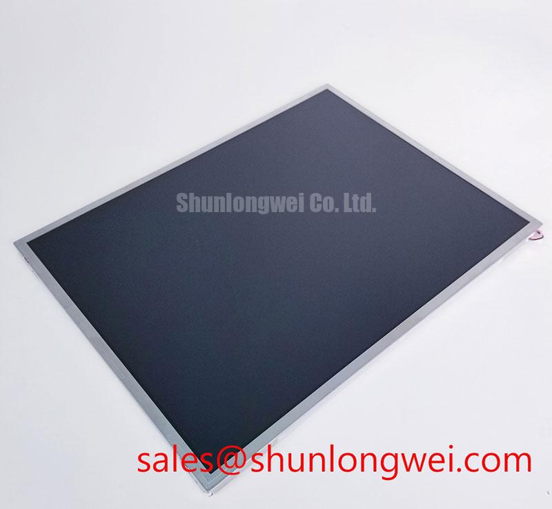
A practical incoming inspection begins with a controlled display test using the original host controller or an approved test source. Allow the panel to reach a stable visual state, then display full-screen red, green, blue, black, and white images one at a time. Record any persistent bright point, dark point, vertical line, horizontal line, localized shadow, or nonuniform region without immediately assigning a cause.
This multi-stage color check separates visible pixel behavior from general illumination behavior. A defect that remains sharply localized through several primary colors may require comparison with the known-good signal path and inspection of the display cable and connector seating. A broad shadow or uneven field may instead justify inspection of the backlight path, diffuser area, enclosure pressure, or optical contamination. These observations are diagnostic clues rather than proof of a specific internal failure.
For automated optical inspection, use the same image files, camera position, ambient lighting, and display warm-up procedure for the replacement and the removed panel. An oblique flashlight inspection with the display unpowered can help reveal surface scratches, pressure marks, frame distortion, or areas that appear mechanically stressed. With the panel operating, oblique illumination can also help distinguish a visible surface or optical irregularity from an active pixel-line defect. This method does not confirm a COG driver fracture, and any suspected line defect should be compared with controlled cable movement and a known-good controller.
Uniformity assessment should be documented across the entire active area, especially near the edges and corners. Uneven mechanical pressure from a bezel or gasket can alter the appearance of an LCD image. The enclosure should therefore be checked for warped brackets, uneven fastener loading, and contact points that press directly against the display assembly. Designers should verify the original mechanical drawing and fastening method rather than imposing a new clamping force on the replacement module.
The available product information does not confirm an LED backlight, a CCFL backlight, a 50,000-hour half-brightness rating, or an MTBF value for this model. Those figures must not be assigned to the NL8060BC21-06 without a model-specific manufacturer document. If the equipment uses a constant-current backlight driver, maintenance personnel should review driver fault records, output stability, open-load behavior, and connector condition. If the system uses another backlight architecture, its service procedure should be followed instead.
For an equipment repair record, retain photographs of the full-screen test, close-up images of suspected defects, the host controller used, and the environmental conditions during inspection. This creates a useful comparison for later service work without presenting an unverified visual threshold as an official acceptance limit.
Radiated Emissions Assessment and Backplate Grounding in Control Cabinets
Pixel jitter, intermittent image loss, and horizontal noise bands should be investigated at the system level. Begin by checking the display signal cable routing, connector retention, shield termination, cabinet bonding, and proximity to variable-frequency motor-drive wiring. A symptom observed near a high-power drive can indicate coupling, impedance discontinuity, grounding weakness, controller instability, or a panel interface problem; an oscilloscope comparison with a known-good signal path is more reliable than assigning a single cause from the image alone.
Multi-point backplate bonding may be evaluated as a Design Consideration where the enclosure construction supports it. The aim is to provide a controlled return path for unwanted high-frequency current while avoiding accidental loops through signal cable shields, mounting brackets, and protective earth conductors. The final grounding arrangement must be determined by the cabinet architecture and verified during system-level emissions testing.
A 360-degree shield termination can be considered when the host equipment documentation and cable construction support that method. It should not be added to the NL8060BC21-06 as though it were a panel-specific factory requirement. Ferrite components are also application-dependent. Their effectiveness depends on cable geometry, common-mode current, frequency range, placement, and the behavior of the complete control system. The correct component and location should be established through measurement rather than by assuming that any ferrite will remove visible display noise.
CISPR Class A or Class B performance belongs to the complete equipment configuration, including the enclosure, controller, cabling, grounding, motor drives, and installation environment. The LCD module itself should not be described as independently certified for the emissions class of a finished machine. When the display is integrated into industrial telematics equipment, engineers should test the final assembly using the compliance plan applicable to that equipment.
Low-temperature operation also requires caution during signal evaluation. LCD response can change with temperature, but the available product data does not provide a verified operating range, gray-to-gray response specification, heater requirement, or liquid-crystal response compensation value for this model. A heater strip, if present in the original equipment, should be controlled according to the equipment manufacturer’s design. The integrator should verify startup behavior after thermal stabilization and compare displayed text, scrolling graphics, and alarm transitions at the intended operating conditions.
For broader enclosure and HMI integration references, engineers can consult Industrial Display & HMI Solutions while keeping the model-specific limits separate from general system design guidance.
Wide-Temperature Operational Margin and Cold-Start Display Response
Do not treat a proposed temperature range as an official rating for the NL8060BC21-06 unless it appears in the applicable NEC documentation. The available product information identifies the product category and construction, but it does not confirm operation from minus 30 degrees Celsius to plus 85 degrees Celsius, storage limits, condensation tolerance, startup time, or gray-to-gray response under cold conditions.
For a machine operating outdoors, the enclosure should be reviewed for heat transfer, airflow, solar loading, condensation, and the transition between a cold shutdown state and energized operation. A display that appears dim, slow, or uneven during cold startup may require comparison with the controller timing, backlight driver behavior, supply stability, and internal condensation condition. The diagnostic sequence should preserve the evidence instead of immediately increasing drive settings or changing the panel cable.
When a PWM backlight controller is part of the host system, its switching frequency and duty-cycle behavior must be verified from the original controller documentation. The frequently used engineering range of 200 Hz to 1 kHz is not a confirmed specification for this NEC module and should not be presented as a guaranteed flicker-free operating window. Designers should evaluate visible flicker, camera interaction, acoustic behavior, thermal performance, and brightness linearity on the complete display assembly.
Backlight protection also belongs to the host driver unless a model-specific panel document states otherwise. Open-load detection, short-circuit response, overvoltage protection, current regulation, and fault reporting should be checked at the driver output with suitable instrumentation. A dark screen can result from a backlight fault, a missing enable signal, a cable problem, a controller fault, or a panel-side issue. Each condition requires a separate measurement path.
Mechanical installation deserves the same attention as electrical commissioning. The front gasket should contact the enclosure continuously without folds or gaps, while the mounting frame should distribute load evenly around the panel. In vibrating equipment, cable service loops and strain relief should prevent connector loading. Maintenance Note: Inspect the cabinet airflow path and gasket condition at scheduled service intervals, particularly after dust exposure or repeated thermal cycling.
Backlight Architecture, High-Voltage Risk, and Service Verification
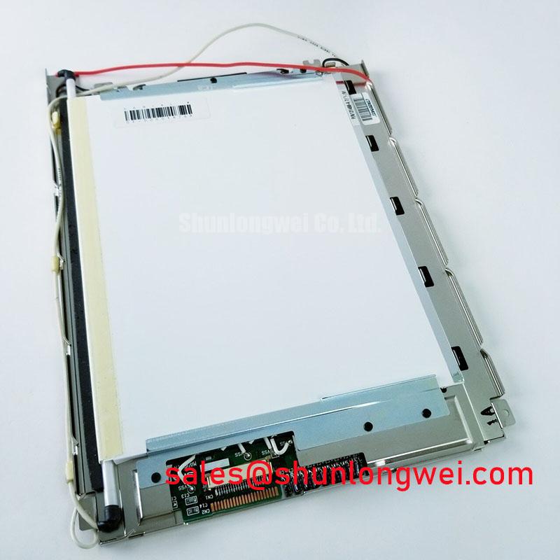
The service engineer should identify the installed backlight architecture from the original equipment drawings before selecting test equipment. The available product information does not confirm whether the NL8060BC21-06 uses CCFL or LED backlighting, nor does it specify an ignition voltage, secondary insulation rating, PWM dimming ratio, acoustic limit, or brightness-life curve. A 1,500 to 1,650 Vrms striking value, a 1,000 to 1 dimming ratio, and a 50,000-hour half-brightness figure must not be attributed to this model without direct supporting documentation.
If the host equipment contains a CCFL inverter, the cold-start circuit should be treated as a high-voltage assembly. Inspect insulation barriers, transformer connections, harness routing, connector condition, and protective interlocks according to the equipment service manual. If the equipment uses an LED constant-current driver, verify the current regulation, enable sequence, open-load response, short-circuit behavior, and overvoltage protection at the driver level. These two architectures require different test procedures and should not be interchanged during troubleshooting.
Backlight faults should be separated from image-generation faults by checking the panel’s video content, the controller status, the backlight enable signal, and the illumination output in a controlled sequence. A faint image, intermittent illumination, or complete darkness may have several possible sources. Compare the suspect assembly with a known-good unit and use the original wiring diagram to identify where the expected signal or supply should be present.
Acoustic buzz should be evaluated as an equipment symptom rather than assigned automatically to the display module. Possible contributors include the inverter, magnetic components, PWM control, mechanical resonance, or mounting pressure. The enclosure should be checked under the same operating condition in which the sound occurs, while electrical measurements remain within the limits of the approved service procedure.
For repair procurement, the essential confirmed identity remains NEC NL8060BC21-06, classified as an Industrial Grade LCD/HMI Panel and TFT-LCD Display Module. Before installation, the system integrator should verify mechanical compatibility, interface requirements, backlight architecture, temperature ratings, and power sequencing from the original panel documentation.