


Content last revised on November 7, 2026
Sharp LQ104V1DG83 Display Identification and Replacement Checks
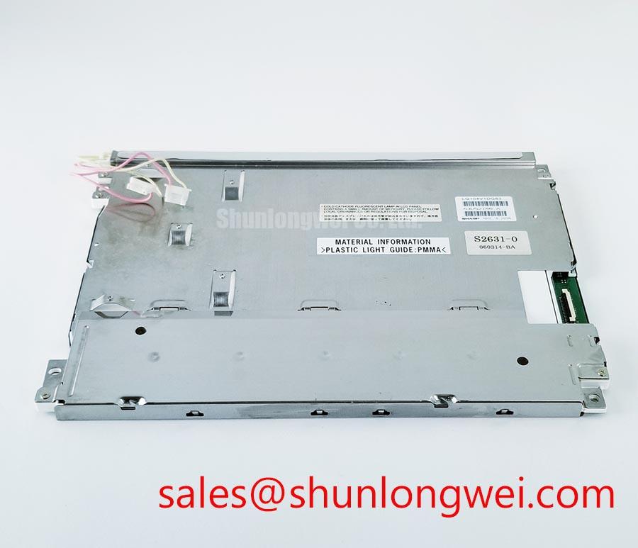
With the display power isolated, check the panel label and cable orientation before connecting a replacement LQ104V1DG83; a matching screen diagonal does not establish connector compatibility. The product specifications are: Manufacturer: Sharp; Part Number: LQ104V1DG83; Diagonal Size: 10.4 inch; Resolution: 640 x 480; Interface: TTL / CMOS. This is a TFT-LCD active matrix color display module, with a parallel interface that must be matched to the host controller rather than treated as an LVDS connection.
For replacement assessment, establish the controller output format, panel connector assignment, mounting geometry, and backlight circuit identity before energizing the assembly. A machine-tool HMI operator terminal is a potential integration application, subject to those checks. Screen size and resolution alone cannot establish electrical or mechanical interchangeability.
Parallel Interface Timing and Noise Verification in High-Vibration Bays
Probe the pixel clock and representative data signals at the panel connector when investigating pixel instability or horizontal noise bands. Design Consideration: Because the LQ104V1DG83 interface is TTL / CMOS, the relevant measurements are single-ended logic levels, clock edge quality, and data setup and hold relationships. Differential eye-diagram analysis applies to an upstream differential link only if the host architecture actually contains one.
Compare the connector waveforms with the panel input requirements and controller output timing while changing the displayed pattern. Alternating pixels and grayscale ramps can expose different timing or data-path problems. Use a suitable probe return connection so that measurement-loop pickup is not mistaken for panel input noise. Where motor-drive activity coincides with an image disturbance, compare signal and supply behavior with that activity enabled and disabled before assigning a cause.
Cable shielding and chassis termination belong to the equipment grounding design, not to an assumed panel accessory package. Designers should assess the shield connection and signal return paths together; adding a ferrite without checking the resulting waveform can obscure rather than resolve the problem. JEIDA and VESA LVDS mapping conventions do not define this panel’s native parallel connector assignment.
Pro Tip: Keep the parallel pixel clock and data routing controlled as a timing group, and validate their relative arrival times at the panel connector rather than assuming differential-pair routing rules apply. During startup and shutdown checks, capture panel power, controller output activity, and backlight enable together. Their sequence should follow the applicable panel and controller requirements, including any interval needed to avoid driving an unpowered input.
Display Thermal Management and Optical Uniformity
Map temperature across the assembled display frame and rear enclosure before changing the mounting arrangement to address uneven brightness. Design Consideration: Thermal gradients and mechanical loading can influence optical uniformity. No quantitative luminance or sunlight-readability claim follows from the LQ104V1DG83’s stated size and resolution.
Evaluate the display at its intended brightness setting after the enclosure reaches a stable operating condition. Compare uniform gray images before and after warm-up, noting whether a disturbance follows a mounting point, an enclosure hot spot, or image content. An aluminum spreader should be considered only where the mechanical and thermal interfaces permit it; avoid introducing a heat path that also loads the display frame unevenly.
For sourcing comparisons, place the Sharp LQ104V1DG83 beside the LQ110Y3DG01 at the specification-review stage, not as an assumed replacement. The comparison below separates established baseline information from items requiring a drawing or datasheet match.
| Selection checkpoint | LQ104V1DG83 | LQ110Y3DG01 comparison requirement |
|---|---|---|
| Manufacturer | Sharp | Consult datasheet |
| Diagonal Size | 10.4 inch | Compare active area and enclosure opening |
| Resolution | 640 x 480 | Match controller output and image mapping |
| Interface | TTL / CMOS | Compare electrical interface and connector assignment |
| Mechanical and backlight compatibility | Consult datasheet and mechanical drawing | Compare mounting points, depth, connectors, and drive requirements |
Temperature-dependent image faults also warrant checking pixel-clock stability and data timing across the equipment’s intended operating conditions. Do not compensate for a timing fault by adjusting gamma settings. Sharp Devices Europe Industrial Display Solutions provides manufacturer context for industrial displays; model-specific limits remain the basis for acceptance testing.
Backlight Identification and Driver Troubleshooting
Identify the installed backlight assembly and its driver connections before selecting an electrical test method. Design Consideration: Backlight ignition voltage, channel count, dimming range, and operating life must not be assigned from another display’s specifications. Where high-voltage backlight circuitry is present, use appropriately rated test equipment and follow the equipment’s electrical safety procedures.
For an illuminated-but-blank screen, inspect image timing and panel power separately from the illumination circuit. For a dark screen, establish whether image information remains visible under suitable external illumination, then examine the driver supply, enable signal, connectors, and fault indication. These observations narrow the investigation without treating one symptom as proof of a failed panel or driver.
When brightness varies unexpectedly, compare the commanded dimming signal with driver output behavior using equipment appropriate to the identified circuit. PWM frequency and duty-cycle response should be selected and validated within that driver’s operating requirements, with checks for visible flicker and acoustic effects. No universal dimming frequency or ignition voltage is a safe prescription for an unidentified assembly.
The LQ104V1DC31 is a separate display-model reference for assessing a related panel-and-driver arrangement, not a backlight driver or an established interchangeable part. Any comparison should include the host power connections and illumination controls. Likewise, evaluate contrast in the intended ambient lighting; do not convert a catalog contrast ratio into a guaranteed sunlight result or infer an anti-glare coating.
Flush-Mount Open-Frame Bezel Integration & Perimeter Gasket Shock Isolation
Check bezel clearance, support locations, and cable exit space against the panel drawing before tightening the assembly. Design Consideration: A perimeter gasket should accommodate the enclosure interface without transferring concentrated pressure into the display surface. Fastener size, tightening torque, and compression limits belong to the actual mounting hardware and mechanical design, not to the screen diagonal.
Inspect uniform dark and gray fields with the assembly supported, then repeat after fastening. A change associated with clamp position or tightening sequence warrants checking frame distortion and gasket loading. Compare observations before modifying the bracket; localized brightness variation can have multiple electrical, optical, and mechanical contributors.
A touch overlay or optical-bonding process adds separate compatibility questions concerning surface loading, adhesive suitability, thermal expansion, and enclosure sealing. The engineering guide A Guide to Resistive, Capacitive, and IR Touchscreens helps distinguish touch-interface choices without implying that this LCD includes a touch sensor. Bonding alone does not establish an environmental protection rating.
Finish the installed-display assessment with grayscale ramps, static interface elements, and viewing-position changes. Check for clipping, color shifts, pressure-related nonuniformity, and residual images after changing content. Preserve the validated controller settings during this comparison; neither an assumed IPS/MVA structure nor an unsupported backlight lifetime curve should determine acceptance of the assembled unit.



