Content last revised on October 19, 2026
Sharp LQ104V1DG64 Product Identity and Integration Boundary
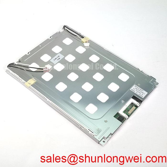
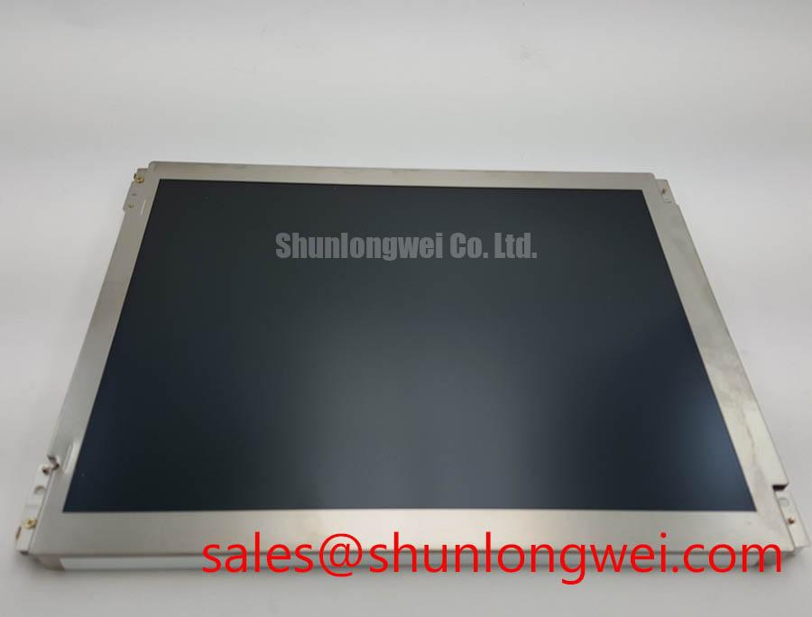
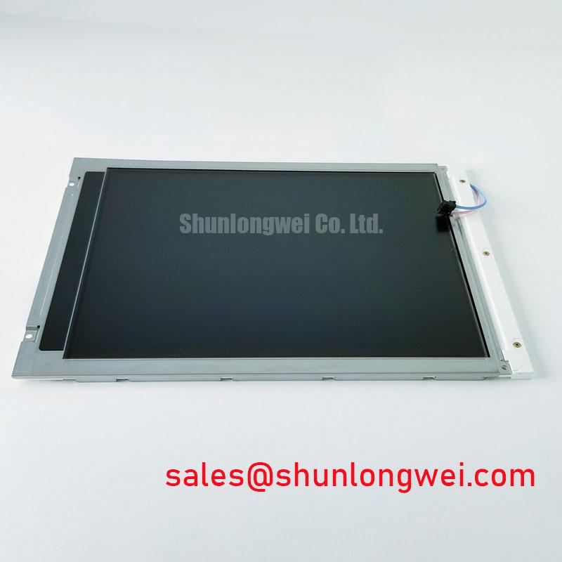
The LQ104V1DG64 is identified as a Sharp TFT LCD active matrix color display module within an industrial LCD and HMI panel category. These are the confirmed product-level identifiers for replacement screening; interface voltage, pixel format, backlight type, optical treatment, timing, and connector pin assignment must be matched against the original equipment documentation before installation.
For a high-voltage substation protection or SCADA dispatch console, the first compatibility decision is physical rather than visual. A panel can produce an apparently correct image while still failing because the connector position, cable exit direction, mounting aperture, or power sequence does not match the host assembly. Compare the removed panel with the LQ104V1DG64 using the equipment drawing, cable markings, controller configuration, and service records. The manufacturer’s industrial display resources at Sharp Devices Europe Industrial Display Solutions and the Sharp Display Solutions Official Portal provide useful context for display-system evaluation.
The product page for this model is available at Sharp LQ104V1DG64. When a same-size replacement review is required, engineers may also compare the mechanical and electrical documentation for NL6448BC33-50 without assuming interchangeability. Connector, timing, backlight, and mounting differences remain system-level acceptance criteria.
Shielded FFC/FPC Flat Flexible Cable Grounding across 360-Degree Connector Shells
Pixel jitter and horizontal noise bands near a variable-frequency motor drive should be investigated through the complete signal return path rather than attributed to the LCD panel alone. Inspect whether the FFC or FPC shield has a continuous, low-impedance connection to the intended connector shell and whether the shell is bonded to the enclosure reference at the correct location. A shield that terminates through a long pigtail or an uncertain chassis path can allow common-mode interference to enter the display interface.
For a 360-degree connector-shell arrangement, the practical objective is uniform shield contact around the cable entry. The cable must not be sharply folded against the shell or compressed by the bezel. Verify cable orientation, contact pressure, latch engagement, and clearance from switching nodes. Common-mode ferrite components may be evaluated as a system design consideration when conducted noise remains after the shield path and cabinet bonding have been corrected. Their impedance profile must match the actual interface edge rate and interference spectrum.
Cold operation changes the visual response of liquid-crystal systems. At sub-zero temperatures, grey-to-grey transitions can appear slower, producing trailing or apparent contrast variation during rapid screen updates. If the host cabinet includes a heater or temperature-control function, the display controller should be checked for its intended enable sequence and fault behavior. Do not add a heater strip or alter its control logic as though it were a supplied feature of the LQ104V1DG64; treat that hardware as an enclosure-level design consideration.
Pro Tip: Keep differential signal routing symmetrical and avoid placing the display cable parallel to high-current motor-drive conductors for long distances.
Dual-Channel CCFL High-Voltage Resonant Inverter Striking Voltage and Ignition Debugging
Before troubleshooting a suspected backlight ignition problem, identify the installed backlight architecture from the original panel documentation and the host inverter. A CCFL ignition procedure must not be applied to an LED assembly by assumption.
For equipment using a dual-channel CCFL inverter, cold ignition is an inverter-system event involving transformer insulation, resonant behavior, lamp condition, cable routing, and protection feedback. An apparent failure to strike can result from an open lamp circuit, degraded insulation, connector contamination, or an inverter protection response. Measure only with probes and instruments rated for the actual high-voltage circuit, and compare both channels under the same operating conditions. Acoustic buzzing should be assessed alongside waveform stability, mechanical vibration, and inverter loading rather than treated as proof of a single failed component.
Where the host system has been converted to an LED backlight, the correct review changes to constant-current regulation, enable logic, PWM behavior, open-load response, and short-circuit protection. A claimed PWM dimming ratio or backlight lifetime must come from the selected LED driver and its thermal conditions, not from the LCD model number alone. The service engineer should preserve the controller’s intended power-up and shutdown sequence so that the panel does not receive an invalid combination of logic, backlight, and video signals.
Constant Luminance Output Control and L70/B50 LED Lifetime Reliability Verification
Stable luminance depends on the complete optical and thermal assembly. When an LED backlight is present, inspect the narrow edge regions of the display for localized heat accumulation, compressed thermal interfaces, and uneven contact with the enclosure. An aluminum spreader rail may be considered where the system design demonstrates a thermal concentration, but its thickness, fastening method, electrical isolation, and clearance must be determined from the enclosure and driver design.
Brightness drift should be separated into driver regulation, LED junction temperature, optical stack condition, and display-controller settings. A service measurement should record luminance at a repeatable instrument position and compare the result with the host system’s normal drive setting. L70 and B50 are reliability metrics that require a defined LED population, drive current, temperature profile, and test method. They should not be presented as confirmed properties of the LQ104V1DG64 without a matching manufacturer specification.
Backlight open-circuit and short-circuit diagnostics are normally handled by the driver. Check whether the host controller reports a fault, disables the enable line, or retries startup. Use the fault output together with current and voltage observations to distinguish a wiring interruption from a driver protection event. In a retrofit, the integrator should also confirm whether the original optical surface is anti-glare, anti-reflective, or untreated; these terms describe different visual behavior under strong cabinet lighting.
Normally White TN Grayscale Inversion Mitigation and Optimal Viewing Direction Alignment
Viewing-direction behavior must be evaluated from the actual installed panel and not inferred from a generic LCD category. A normally white TN configuration can show grayscale inversion when viewed away from its preferred axis, while IPS or MVA technologies have different contrast and angular characteristics. The LQ104V1DG64 should therefore be judged in the final SCADA console position, including the operator’s standing and seated sight lines.
For a substation dispatch console, examine dark grey alarm screens, thin trend lines, and small text from the normal viewing direction. If grayscale steps reverse or lose separation, adjust the panel orientation or the user interface contrast strategy only after confirming that the effect is inherent to the display technology rather than a timing or video-format mismatch. JEIDA and VESA data formatting, bit order, clock polarity, and link timing must agree with the controller configuration.
Surface treatment also affects readability under high ambient illumination. An anti-glare surface can reduce reflected highlights, while an anti-reflective treatment addresses reflection through a different optical mechanism. Inspect the replacement panel under the actual cabinet lighting and verify that the bezel does not introduce a bright reflection across alarm text. PWM backlight control should be checked for audible artifacts, visible flicker, and duty-cycle response across the intended brightness range. The system integrator should validate the selected control frequency and dimming behavior with the installed driver rather than impose a generic setting.
For broader enclosure, interface, and environmental assessment, the engineering reference Industrial Display & HMI Solutions can be used alongside the equipment manufacturer’s service documentation.