

Content last revised on September 10, 2026
LM64P89L Sharp Industrial LCD Display Module for HMI Applications
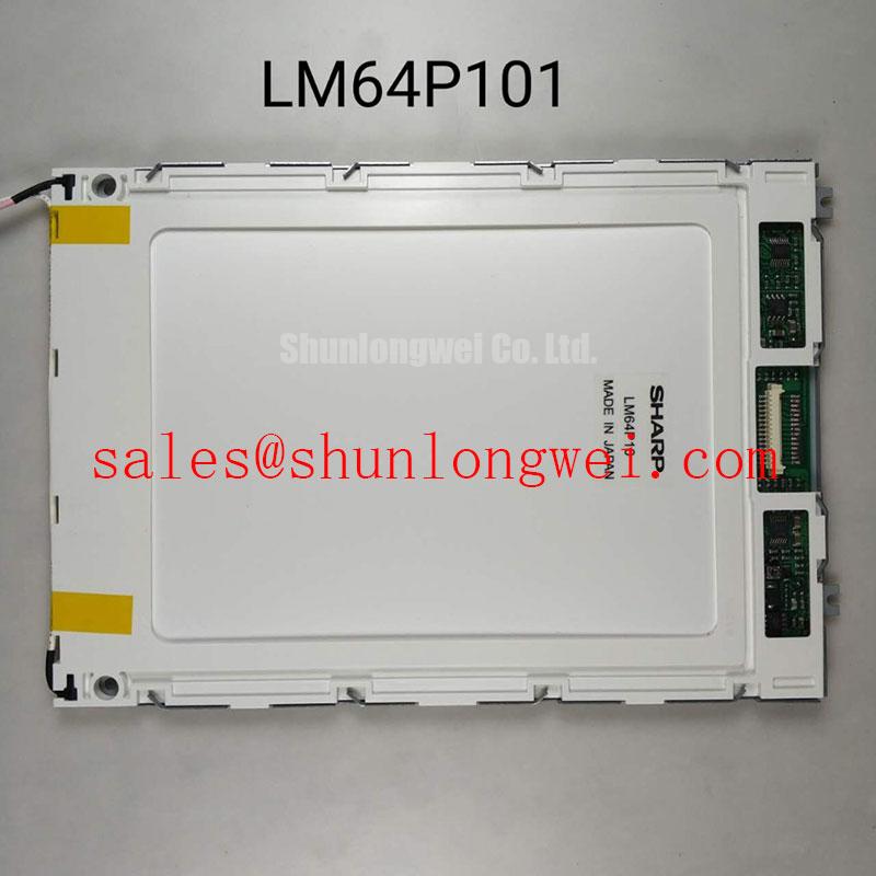
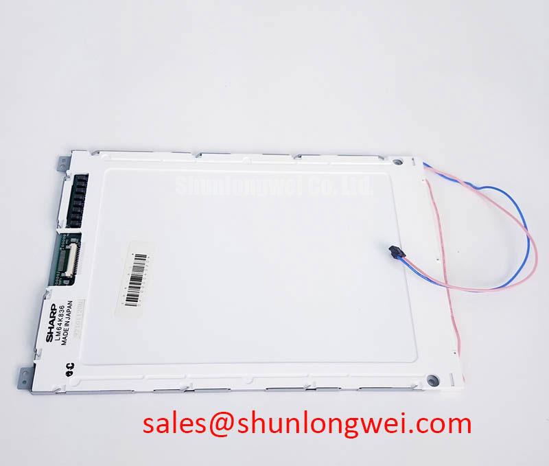
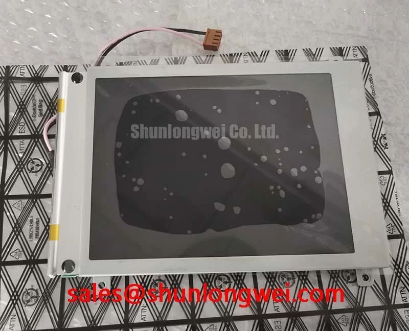
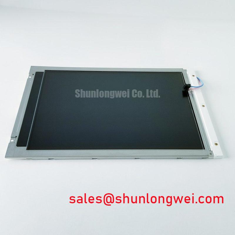
Inspect the LM64P89L display module under controlled illumination before installation, checking the visible panel surface, frame, connector area, and label against the maintenance record. This incoming QA sequence establishes whether the part is suitable for further electrical testing without assuming unverified interface or optical data.
The LM64P89L is identified in the supplied factory context as a Sharp TFT LCD Display Module in the industrial-grade LCD and HMI panel category. The available product identity confirms the manufacturer, product category, and display-module construction; it does not confirm a particular diagonal size, pixel format, interface voltage, backlight type, luminance value, contrast ratio, response time, or operating-temperature range. Those values should be taken from the original panel documentation or the equipment manufacturer’s approved service record before electrical substitution.
| Parameter | Available product information | Engineering handling |
|---|---|---|
| Model | LM64P89L | Use the complete model marking during procurement and service evaluation. |
| Manufacturer | Sharp | Confirm the original equipment documentation before integration. |
| Product category | Industrial Grade LCD/HMI Panel | Evaluate as a display module within the host HMI assembly. |
| Package or enclosure | TFT-LCD Display Module | Verify mechanical envelope, mounting points, and connector clearance from the original assembly. |
| Specification status | Product identity information available | Use confirmed factory data for final electrical and environmental approval. |
For a hazardous petrochemical Zone-2 explosion-proof operator station, the display is only one element inside a certified equipment architecture. The host enclosure, cable glands, viewing window, power system, control electronics, thermal management, and applicable hazardous-area approval remain system-level responsibilities. The LM64P89L should therefore be assessed as a replacement or integration candidate only after the responsible engineer confirms dimensional, electrical, optical, and certification compatibility.
During bench work, isolate the panel from the host controller and document the original cable orientation before removal. A visual inspection under even white light can reveal scratches, pressure marks, liquid ingress traces, frame deformation, or contamination near the connector. These observations do not identify a single failure mechanism by themselves, but they help separate handling damage from faults that require signal-path testing.
Backlight Thermal Dissipation and Light Guide Preservation
The supplied factory information does not confirm whether the LM64P89L uses an edge-lit LED rail, a CCFL assembly, or another backlight arrangement. Do not assign a backlight technology from the model number alone. The system integrator should verify the required backlight type, drive method, connector pinout, current requirements, and optical stack from the original panel documentation before applying power.
When the original assembly uses an edge-lit arrangement, thermal review should begin at the narrow display edges where the backlight source and mechanical frame can create localized heating. This is a Design Consideration, not an official LM64P89L thermal specification. A heat-spreading rail may be evaluated where it can transfer heat into the approved chassis without loading the glass, distorting the frame, obstructing the optical path, or creating a new conductive path near high-voltage circuitry. The final structure must be tested in the completed enclosure rather than judged from the panel alone.
Claims about PMMA light-guide composition, yellowing resistance, L70 or B50 performance, and backlight lifetime are not established by the supplied factory parameters. These characteristics require a manufacturer datasheet, reliability report, or system test record. In a repair evaluation, inspect the active area for brightness bands, edge hot spots, color drift, and nonuniformity after the display reaches a stable operating condition. Compare the result with a known-good unit using the same camera exposure, viewing angle, input image, and ambient lighting.
Cold operation requires a separate check because liquid-crystal response can change as temperature falls. The supplied data does not establish operation from −20°C to −30°C, nor does it specify gray-to-gray behavior in that range. If the host equipment is expected to start in a cold environment, the integrator should measure image response after cold soak and during warm-up. A controlled heater strip may be considered only when its placement, control loop, insulation, and surface temperature have been validated against the display manufacturer’s limits. Heating the panel locally can produce optical nonuniformity or mechanical stress if it is applied without a thermal survey.
For a high-brightness operator station, verify the complete optical path through the enclosure window, gasket, protective cover, and any anti-reflection treatment. A bright panel viewed through a contaminated or poorly sealed window can appear to have a display fault when the loss is actually outside the module. The same distinction matters when assessing glare, sunlight readability, or apparent contrast in a field monitoring terminal.
Display Interface Mapping and Even and Odd Channel Integrity
Before connecting the LM64P89L, identify the host controller interface from the original wiring diagram and panel service documentation. The supplied factory data does not confirm LVDS, TTL, VESA mapping, JEIDA mapping, connector pin assignments, logic-supply voltage, power-on timing, clock polarity, or data-hold requirements. The system integrator should verify the required supply voltage from the original panel documentation rather than selecting between commonly used voltage options by assumption.
VESA and JEIDA are not interchangeable labels for a casual cable swap. A mapping mismatch can present as incorrect colors, split-screen content, swapped pixel significance, unstable synchronization, or an image that appears partially valid. These symptoms can also arise from connector seating, cable damage, transmitter configuration, grounding, or timing incompatibility. The correct diagnostic method is to compare the suspected panel with the known-good signal path and confirm the transmitter setup in the controller configuration.
Routing should preserve the intended differential geometry and return-current path. A Design Consideration for an LVDS link is to maintain the characteristic impedance specified by the transmitter, receiver, and cable assembly; a commonly encountered 100-ohm differential target must not be treated as an LM64P89L factory requirement unless the original documentation states it. Keep the cable away from noisy switching nodes, avoid unnecessary stubs, and ensure that shield termination follows the host equipment’s EMC design. The display module itself cannot be described as independently certified for the completed machine’s EMC performance.
Power sequencing is equally important during replacement work. The proposed controller timing must be checked against the panel documentation, including supply rise, reset behavior, enable signals, clock availability, and backlight activation. The timing interval sometimes used by a controller design is not automatically valid for this Sharp module. Observe the panel supply and control lines with an oscilloscope during startup and shutdown, then compare the waveform order with the approved reference design. White-screen behavior, residual images, or intermittent startup may indicate a sequencing or signal-integrity issue, but the waveform evidence should determine the next test rather than a single symptom.
💡 Bench Tip: Disconnect power before inserting or removing the display cable, and lock the connector only after the flex or cable is fully aligned and seated without lateral force.
For equipment exposed to vibration, inspect the cable retention path after thermal cycling and enclosure assembly. A connector that works on an open bench can behave differently when the cable is bent by the cover or pressed against a bracket. The final test should include the installed cable route, the actual controller, and the enclosure grounding arrangement.
Backlight Acoustic Noise and EMI Evaluation Across PWM Operation
The supplied parameters do not identify the LM64P89L backlight as CCFL or LED, and they provide no confirmed ignition voltage, PWM input range, dimming ratio, acoustic limit, or half-life value. The integrator should verify the backlight architecture from the original documentation before selecting a driver. Applying a CCFL inverter to an LED assembly, or an LED driver to a CCFL assembly, is not a valid compatibility experiment.
If the original system includes a high-voltage backlight circuit, keep ignition and running measurements within the driver and panel specifications. If it uses a constant-current LED driver, evaluate current regulation, enable behavior, brightness uniformity, and the relationship between dimming command and measured luminance. PWM frequencies such as the commonly used 200 Hz to 1 kHz range may be encountered in industrial systems, but they are not confirmed specifications for this model. Any proposed frequency and duty-cycle range should be treated as a Typical Starting Point for controlled bench evaluation, followed by flicker, acoustic, and thermal measurements in the final assembly.
Acoustic noise should be localized with the panel operating under the same load and brightness conditions used in the machine. A buzz may originate in the driver, transformer, capacitor, enclosure panel, or mounting structure. Do not attribute it to the display module without isolating the source. Record the sound with the enclosure assembled because covers and brackets can amplify vibration that is barely audible on the bench.
EMI assessment belongs to the complete host system. Cable routing, driver switching edges, enclosure bonding, grounding, and filter placement can all affect emissions. The LM64P89L should not be represented as independently passing CISPR, EN 55011, or another system-level EMC certification. The responsible compliance engineer must test the finished operator station against the standard and installation category that applies to the equipment.
Do not publish a guaranteed service life, MTBF, or 50,000-hour half-life for this model without a source that explicitly applies to the exact panel and operating conditions. Brightness retention depends on the backlight, temperature, drive level, duty cycle, enclosure heat, and optical environment. A repair record should therefore capture initial luminance and uniformity measurements when those values are required by the customer’s acceptance procedure.
Mitigating Gray-to-Gray Response Changes During Cold-Start Power-Up
Cold-start evaluation should begin with the installed panel at the actual machine temperature, followed by a controlled startup sequence using the approved controller. The supplied factory information does not specify gray-to-gray response time, cold operating limits, contrast ratio, anti-glare coating, direct-sunlight performance, or perimeter seal construction for the LM64P89L. These properties must be verified from the original Sharp documentation or measured on the completed assembly.
Liquid-crystal response can become slower as temperature changes, but the magnitude and acceptable behavior are panel-specific. Test several representative transitions rather than relying on a single moving image. Use static text, alarm indicators, trend graphics, and rapidly changing status fields because an operator station may show all of these during startup. Record the time required for the image to become usable and check whether the controller is sending valid frames throughout the warm-up period.
If a heater or enclosure warming strategy is considered, it should be controlled by the system designer with attention to condensation, local temperature gradients, cable flexibility, and the panel manufacturer’s limits. The objective is to establish a stable operating condition without imposing a hot spot on the glass or frame. A delayed image may also be associated with controller initialization, backlight enable timing, cable integrity, or an unsuitable signal mode, so verify the complete startup waveform before changing the thermal design.
For sunlight-facing equipment, evaluate the display through the actual viewing window at the intended angle and illumination. A claimed contrast ratio above 500:1 at 50,000 lux is not supported by the supplied factory data and must not be assigned to this model without a documented measurement basis. Check the visibility of small text, alarm colors, dark gray transitions, and reflected highlights. The window, coating, seal, and mounting hood can influence the result as much as the panel.
Long-duration static HMI screens also require system-level observation. The supplied information does not establish image-retention or burn-in performance. Designers should rotate fixed screen elements where the application permits, use the host controller’s approved screen-management functions, and verify whether any persistent pattern remains after normal content changes. A retained image can involve panel history, drive conditions, temperature, or controller behavior; diagnosis should use controlled image patterns and a documented recovery interval rather than a single visual impression.
For a potential Zone-2 operator-station installation, review the complete environmental and certification boundary before approval. The Industrial Display & HMI Solutions reference can support broader enclosure and maintenance planning, while dimensional and electrical acceptance for the Sharp module must remain tied to the original equipment documentation. Where a same-class replacement evaluation is required, engineers may also compare the published information for LM64P10, without treating that comparison as a compatibility guarantee.