Content last revised on September 13, 2026
HLM8620-6 Inspection and Compatibility Overview
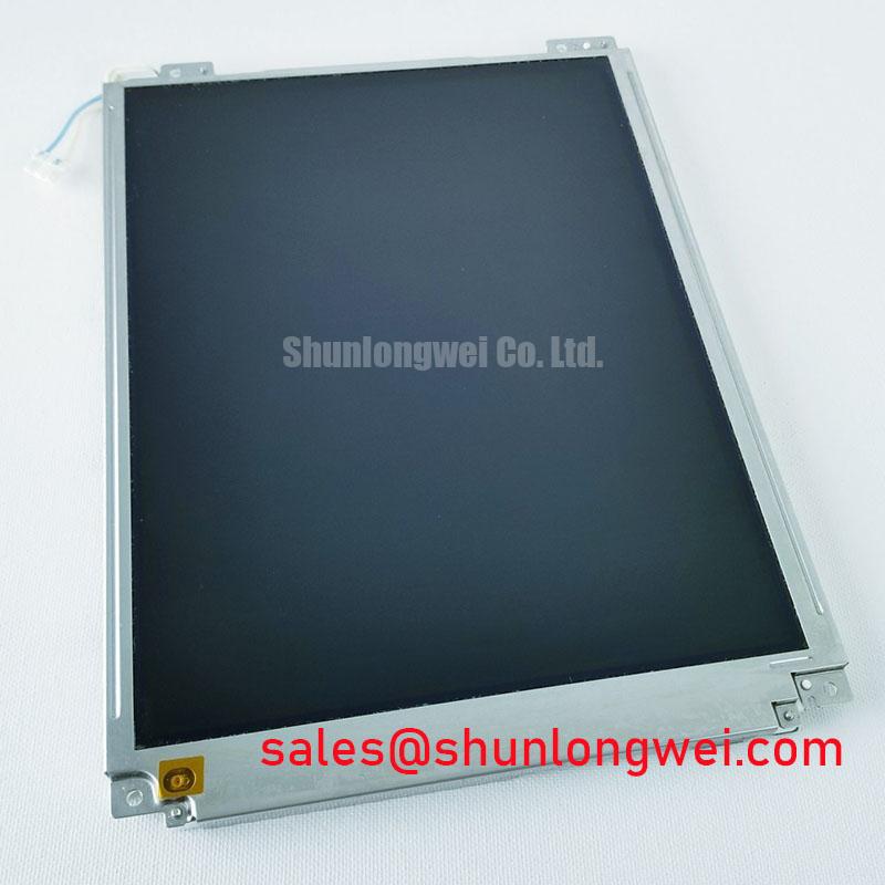
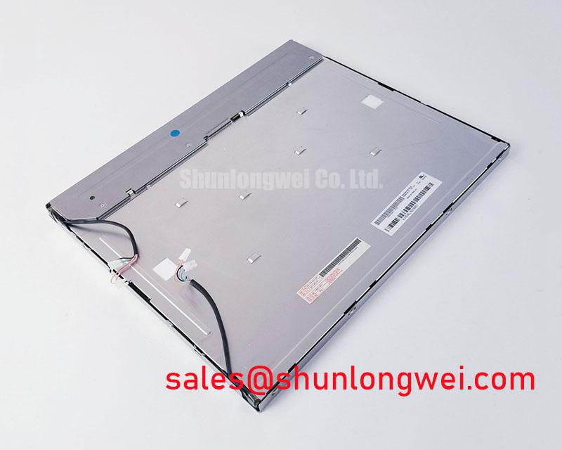
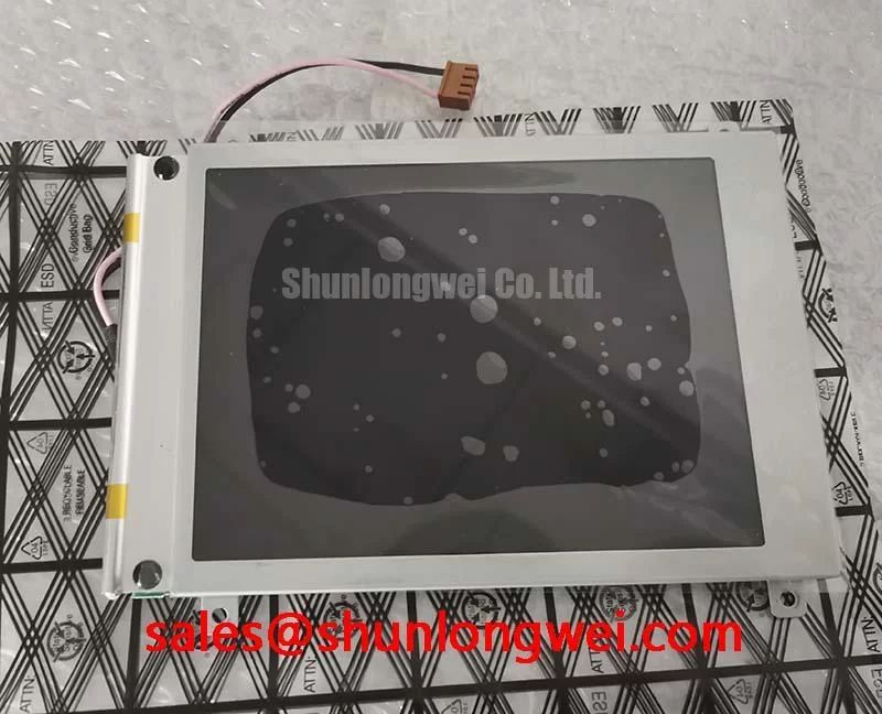
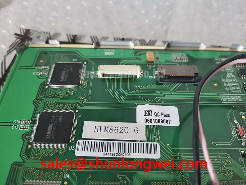
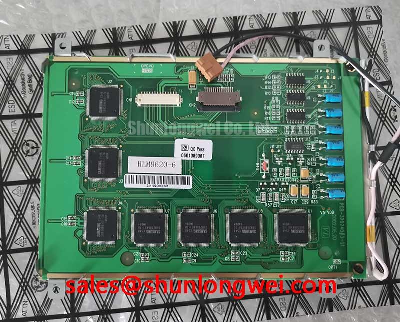
With power isolated, inspect the HLM8620-6 TFT-LCD display module for bezel distortion, connector displacement, cracked glass, and visible contamination before applying any bench signal or backlight power.
The AUO HLM8620-6 is identified in the supplied factory context as an Industrial Grade LCD/HMI Panel with a TFT-LCD display module construction. The available official product data confirms the manufacturer, product category, display-module form, and official factory specification status. It does not provide a verified panel resolution, active-area dimension, luminance value, supply voltage, interface assignment, touch technology, backlight electrical rating, temperature range, contrast ratio, or mechanical drawing. Those values should therefore be checked against the original AUO documentation and the equipment service file before replacement approval.
| Model | HLM8620-6 |
| Manufacturer | AUO |
| Product category | Industrial Grade LCD/HMI Panel |
| Display construction | TFT-LCD Display Module |
| Specification status | Official Factory Spec Verified |
For maintenance teams, this distinction matters. A mechanically compatible display is not automatically electrically compatible. The replacement review should compare the original panel label, connector keying, cable routing, timing controller requirements, backlight driver arrangement, mounting points, and touch interface. The system integrator should verify the required supply voltage from the original panel documentation rather than infer it from the model number.
High-Humidity Storage Margins and Delamination Prevention Protocols
When an HLM8620-6 has been stored in a humid workshop, begin with a dry visual inspection rather than immediately connecting it to a CNC operator panel or robot teach pendant. Look for edge whitening, moisture residue, adhesive separation, corrosion near the connector, and changes in the viewing surface. These observations do not prove a particular internal failure, but they help determine whether controlled conditioning and additional inspection are appropriate.
The supplied factory context does not publish a verified humidity qualification, storage limit, operating temperature range, liquid-crystal response curve, sealant specification, or optical contrast rating for this model. Avoid presenting a generic industrial temperature cycle as an HLM8620-6 guarantee. If the equipment documentation specifies operation across sub-zero and elevated temperatures, evaluate the complete assembly rather than the panel alone. Liquid-crystal viscosity can affect perceived response at low temperature, while thermal expansion differences between the display, bezel, cable, and chassis can increase mechanical stress during cycling. These are Design Considerations, not model-specific factory claims.
For a field assessment, compare the suspect display with a known-good signal path at room conditions, then repeat the visual check after the assembly has stabilized at the intended service temperature. Observe whether gray transitions, dark areas, or edge uniformity change with temperature. A slow gray-to-gray transition may involve panel timing, source signal conditions, temperature, or the display electronics; it should not be assigned to viscosity alone without controlled comparison.
Direct sunlight testing also requires caution. The supplied data does not verify a contrast ratio above 500:1 at 50,000 lux, nor does it confirm an anti-glare or anti-reflective surface treatment for the HLM8620-6. In a sunlit control cabinet, inspect the display at the actual viewing angle and measure the installed system under representative illumination. The result depends on the panel, cover window, surface treatment, ambient reflection, backlight condition, and enclosure geometry.
Humidity protection is usually a system responsibility. Designers should review enclosure sealing, condensation control, cable-entry conditions, and warm-up behavior. The display should be allowed to reach a stable condition before powered evaluation when condensation is possible. For background on TFT-LCD selection, operating principles, and common assumptions, consult The Ultimate Guide to Industrial TFT LCD Technology.
Full-Screen Primary Color AOI Screening and Background Uniformity Audit
Use full-screen red, green, blue, white, black, and mid-gray images during incoming inspection, provided that the host controller and display interface are correctly matched. First inspect for stuck or missing sub-pixels. Next examine large-area brightness variation and color shading. Finally use a low-angle flashlight in a darkened area to identify whether a shadow follows the illuminated region, remains fixed at the edge, or appears only when the backlight is active.
This three-stage check is an Engineering Recommendation for separating visible symptoms, not a factory acceptance limit for the HLM8620-6. A dark region can involve the backlight path, optical stack, display driving conditions, cable contact, or panel electronics. A line defect can also be associated with the signal path or bonded driver area. Confirm the observation by checking the same image through a known-good controller and by inspecting the connector without applying mechanical force.
The official data supplied for this product does not identify a TTL or LVDS interface, transmitter clock specification, data hold time, differential impedance, or allowable clock-jitter margin. Do not connect a presumed LVDS cable or TTL source based only on connector appearance. The system integrator should verify the original interface documentation, signal naming, lane order, logic levels, timing sequence, and cable pinout before energizing the panel.
Where a differential display link is confirmed by the original documentation, controlled impedance routing and matched pair geometry are common Design Considerations for reducing reflections and timing uncertainty. A frequently used industry starting reference is 100 Ω differential impedance, but it must not be treated as an AUO HLM8620-6 factory requirement without a source specific to the installed interface. Oscilloscope verification should compare clock and data behavior at the panel connector against the known-good system, especially when a servo drive or inverter operates nearby.
AOI results should be recorded by display area rather than described only as “bad screen.” Note whether a defect is fixed to the glass position, changes with the video source, follows cable movement, or varies with backlight enable. That record helps the repair engineer distinguish a panel-level observation from an upstream controller, power, or harness issue without making a single-cause diagnosis.
Field Alert: Disconnect system power and follow the equipment discharge procedure before inserting or removing the display cable, because signal-pin contact during live connection can create an avoidable electrical fault.
Diffuser Film and Prism Sheet Thermal Buckling Prevention During Continuous Full-Duty Operation
In continuous-duty equipment, inspect the installed display for localized bright zones, dark corners, color drift, and patterns that become more visible after prolonged operation. Record the cabinet airflow condition, nearby heat sources, controller temperature, and backlight state. The supplied factory information does not confirm the HLM8620-6 optical-film materials, LED lifetime rating, L70 or B50 values, diffuser construction, prism-sheet specification, or internal heat-spreader design. Those characteristics should not be inferred from the TFT-LCD category.
Thermal management should begin with the complete assembly. Designers should avoid placing heat-producing regulators, braking resistors, servo electronics, or poorly ventilated power components directly behind the display unless the resulting temperature has been measured and accepted against the original equipment limits. Edge rails, brackets, and heat-spreading parts may be evaluated where they do not press against the display or obstruct the intended optical geometry. This is a system-level Design Consideration rather than a prescribed HLM8620-6 modification.
Mechanical restraint is equally important. A display that appears uniform on the bench can show mura after installation if the bezel, rear support, cable bend, or mounting frame introduces uneven pressure. Check the chassis for burrs and twist, confirm that the panel sits naturally in its opening, and inspect the image before and after final fastening. If the defect appears only after assembly, compare the fastener condition and frame alignment before replacing the panel again.
High-frequency factory equipment can also disturb the display link. Maintain a clean separation between display cables and high-current motor or brake wiring where the cabinet layout permits. Use the original shield termination and grounding arrangement unless the equipment manufacturer specifies another method. For a confirmed differential interface, 100 Ω ± 10% is a common Design Consideration for controlled differential routing, while pair skew and clock-jitter acceptance remain dependent on the transmitter, receiver, cable, and panel timing specification. The system engineer should verify the complete link with the actual cable and controller.
Do not claim that the HLM8620-6 independently carries EMC approval for a complete CNC machine or robot control system. EMC behavior belongs to the assembled equipment, including its power supply, enclosure, cable shields, grounding, controller, and switching loads. When the display is used near a voltage-source converter or other power topology, the relevant system-level switching environment can be reviewed alongside background material on Modular Multilevel Converter systems. Polyimide film may appear in surrounding high-voltage assemblies, but the supplied HLM8620-6 data does not establish such material inside this display; general dielectric information is available from Polyimide Film High Voltage Dielectric Insulation.
Chassis M3 Fastener Torque Sizing and Optical Mura Control
Before mounting the HLM8620-6 into an industrial HMI, measure the opening and compare the chassis drawing with the original panel assembly. The supplied factory parameters do not include a verified outer-bezel envelope, hole pattern, M3 fastener torque, panel thickness, or allowable mounting tolerance. Do not use an assumed torque value as an official AUO requirement unless it is confirmed by the applicable mechanical drawing or service manual.
As a general Design Consideration, fasteners should secure the display without bending the frame or loading the active area. Use the original hardware where possible, keep washers and spacers in their documented positions, and tighten progressively in a cross pattern when the chassis design requires multiple mounting points. The correct torque is determined by the fastener, thread material, bracket design, panel frame, washer arrangement, and equipment manufacturer instructions. A torque value suitable for one bezel cannot be transferred automatically to another assembly.
Inspect the display on a black and mid-gray image before final tightening, then repeat the inspection after the bezel is secured. Compare edge shadows, corner brightness, and broad cloudy areas. If mura develops only after installation, release the mechanical load according to the service procedure and check frame flatness, cable routing, gasket position, and contact points. This approach avoids treating every post-installation optical change as a permanent panel defect.
Anti-glare and anti-reflective performance should also be verified from the actual operator position. The official information supplied here does not confirm a particular AG or AR coating, nor does it verify contrast stability above 500:1 under 50,000 lux. A cover lens, protective film, fingerprints, overhead lighting, and cabinet angle can materially alter readability. For a CNC operator panel or robot teach pendant, evaluate the installed viewing surface with the same gloves, illumination, and screen content used by operators.
Touch functionality must be checked separately from the LCD image. The available factory context does not confirm whether this assembly includes a resistive, capacitive, or other touch technology. Confirm the original touch controller, interface, glove requirement, water tolerance, calibration procedure, and protective overlay from the equipment documentation. A working image does not prove that the touch layer or its controller is compatible.
When installation is complete, verify power sequencing, display timing, backlight control, touch response, cable retention, and image uniformity as one assembled system. Record the measured observations and the documentation used for each acceptance decision.