Content last revised on September 13, 2026
A080SN01 V8 AUO Industrial TFT LCD Display Module
| Model | A080SN01 V8 |
| Manufacturer | AUO |
| Product category | Industrial Grade LCD and HMI Panel |
| Construction | TFT LCD Display Module |
| Specification status | Factory Identity Verified |
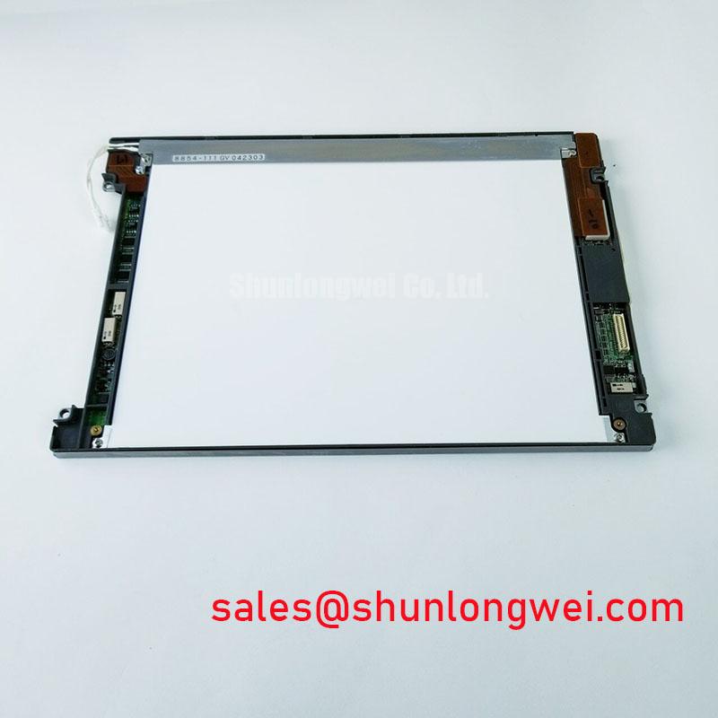
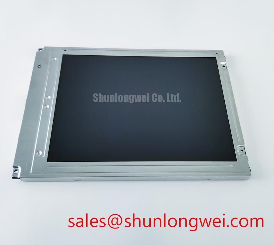
Inspect the panel frame, connector area, bezel contact surfaces, and visible display area before installation, then compare the model marking with the original equipment documentation. The A080SN01 V8 is an AUO industrial TFT LCD display module intended for evaluation in HMI panels, control cabinets, monitoring terminals, and other equipment where the original display assembly must be matched by its documented electrical and mechanical interfaces.
This product page records the available factory identity without adding unverified values for resolution, viewing angle, supply voltage, connector pin count, backlight type, luminance, or operating temperature. Those values can vary between panel revisions and system configurations. The system integrator should verify every interface requirement against the original AUO panel documentation and the equipment service manual before applying power.
Eye Diagram Voltage Margin and Differential Noise Floor Verification in High Vibration Bays
When the A080SN01 V8 is evaluated inside a control cabinet or signalling enclosure, the first practical check is the complete signal path rather than the display alone. Inspect the flexible cable routing, connector retention, shield termination, grounding arrangement, and proximity of differential signal cables to motor drive conductors. Variable frequency drives and switching power stages can introduce common mode energy that appears as intermittent pixel jitter, horizontal noise bands, or unstable image data.
Design Consideration: A shielded FFC or LVDS cable should be integrated according to the panel and controller documentation, with the shield reference arranged to avoid uncontrolled ground current through the display frame. If ferrite suppression is used, its impedance characteristics and placement should be selected from measured common mode noise rather than treated as a universal cure. The chassis bonding strategy, cable length, connector construction, and cabinet earthing all influence the result.
For a system using differential display signaling, the designer should verify the required differential characteristic impedance and pair skew budget from the controller and panel interface specifications. Eye diagram measurements should be taken at the receiving interface under the actual cabinet load, vibration condition, cable routing, and converter operating state. A poor eye opening may indicate signal integrity, grounding, timing, or power quality concerns; compare the suspect path with a known good assembly and confirm the supply rail and clock relationship before replacing the panel.
Power disturbances should also be investigated at the display connector during motor acceleration and regenerative events. Equipment containing a battery management system or a supercapacitor energy buffer may have additional transient behavior, but those external system references do not establish an electrical rating for the A080SN01 V8. The panel’s own limits must come from its applicable documentation.
Suppressing Localized Thermal Gradients to Prevent Chronic Optical Yellowing
Before fitting the display into a cabinet cutout, check that the mounting surface is flat and that the frame is supported evenly. Uneven compression can transfer mechanical stress into the display assembly and can also create local gaps that allow dust or heated air to enter. A narrow metal rail or frame member should not press directly against an unsupported display edge unless the panel documentation permits that arrangement.
Design Consideration: Heat spreading around a display should be based on measured temperature distribution, airflow, enclosure construction, and the verified backlight architecture. Do not assume that a particular optical polymer, LED arrangement, brightness rating, or lifetime curve applies to this model without a supporting AUO specification. Localized heating may contribute to long term color shift, brightness nonuniformity, or adhesive ageing, but the actual mechanism must be confirmed through temperature measurement and inspection of the complete display assembly.
During a thermal evaluation, record temperatures at the display frame, controller area, cable entry, and nearby heat sources while the equipment operates at its intended brightness and refresh conditions. Check the result after the enclosure has reached equilibrium, then repeat the inspection after a cold start. If the system uses constant current backlight control, the driver’s current regulation, dimming behavior, heat dissipation, and fault response should be verified separately. The A080SN01 V8 should not be assigned a backlight MTBF or L70 value unless that value is present in the applicable factory documentation.
For potential use in railway passenger information systems or cab signalling displays, enclosure designers should also consider sunlight loading, forced air paths, vibration, and service access. These are integration conditions, not evidence that the panel is certified for a specific railway application.
20 Pin and 30 Pin Differential LVDS Timing, Pixel Clock and Skew Compensation
Do not select a replacement cable by appearance alone. Inspect the original connector keying, contact count, cable orientation, controller board designation, and panel interface drawing. The A080SN01 V8 product identity supplied here does not confirm a 20 pin or 30 pin connector, a particular LVDS mapping, or a specific logic supply voltage. The system integrator should verify the required supply voltage from the original panel documentation.
Where the verified interface uses LVDS, the controller and display must share the same data mapping convention and timing relationship. JEIDA and VESA mapping should be confirmed from the original documentation rather than inferred from connector placement. Pixel clock, data enable behavior, frame timing, and power on sequencing should be checked with an oscilloscope or logic analyzer during startup. Split screen images, incorrect colors, or unstable synchronization can arise from mapping errors, timing mismatch, cable orientation, or inadequate power sequencing, so the complete signal path should be tested.
If the panel assembly includes a documented PWM dimming input, the integrator should verify the permitted frequency range, duty cycle behavior, polarity, and logic level from the relevant specification. Flicker perception, audible behavior from the driver, and brightness linearity depend on the backlight driver and the optical system as well as the panel. Do not apply a generic PWM value to an undocumented input. Confirm the controller output and the display response under minimum and maximum brightness commands.
For hardware replacement evaluation, the TCG084SVLQAPNN-AN30-S may be reviewed as a separate display option, but compatibility must be established from documented dimensions, connector assignment, timing, mounting details, and optical requirements. A similar diagonal size does not establish a direct replacement relationship.
High Humidity Storage Margins and Delamination Prevention Protocols
Store and transport the A080SN01 V8 in accordance with the manufacturer’s handling documentation, with protection against condensation, contamination, impact, and uncontrolled temperature changes. If a cold panel is moved into a warm humid cabinet, allow the assembly to reach a stable condition before energizing it. Moisture on connectors, cable contacts, or the panel perimeter can produce temporary behavior that is difficult to distinguish from a permanent electrical fault.
Design Consideration: A humidity evaluation should define the complete enclosure condition, including air circulation, sealing strategy, desiccant practice, storage duration, and recovery inspection. The stated product information does not establish a qualified 60°C and 90% RH storage rating for this model, so that condition must not be presented as an AUO specification. Any environmental test should be agreed with the equipment owner and supported by the applicable panel documentation.
At sub zero temperatures, liquid crystal response can become slower and image transitions may require additional settling time. This is a general display technology consideration, not a confirmed performance limit for the A080SN01 V8. Engineers should verify gray to gray behavior, startup recovery, contrast, and image uniformity across the intended thermal range using the actual controller and backlight settings. Perimeter sealing, frame pressure, and cable strain should be inspected after thermal cycling because delamination or optical nonuniformity can be influenced by the full mechanical stack.
Maintenance Note: De energize the equipment before disconnecting the display cable, and periodically inspect cabinet airflow paths and sealing pads for dust loading, compression damage, or loss of contact.
For the underlying principles of industrial TFT display selection and integration, consult The Ultimate Guide to Industrial TFT LCD Technology. It should be used as technical background, while the A080SN01 V8 interface and environmental limits remain subject to the applicable AUO documentation.