

Content last revised on September 10, 2026
Polarizer Durability & Optical Retardation Film Inspection under Direct Industrial Lighting
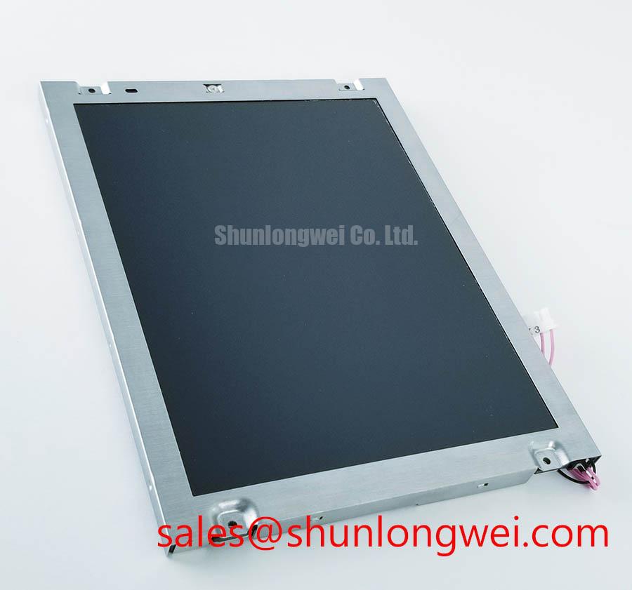
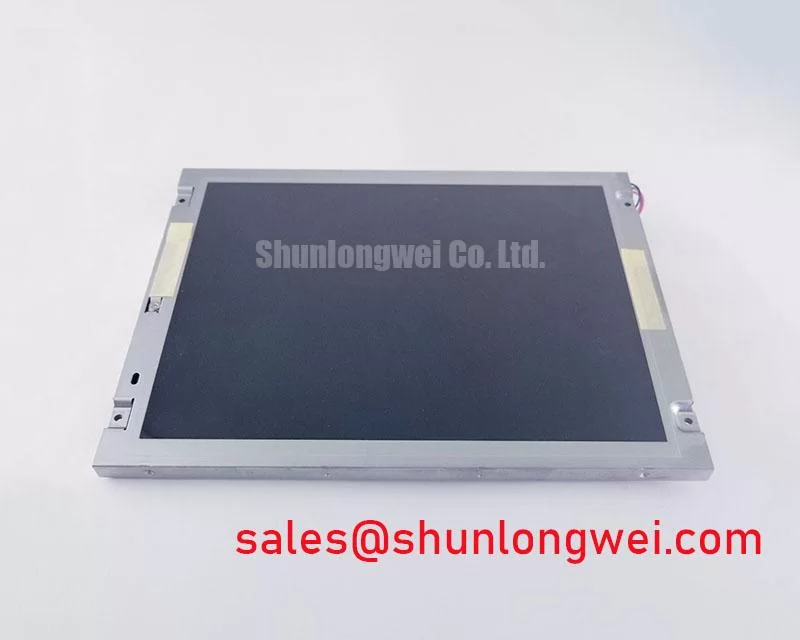
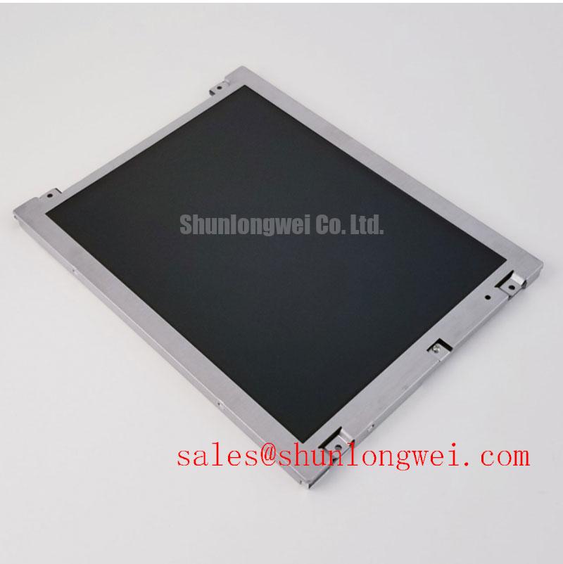
Direct industrial lighting can make a display appear defective when the actual issue is surface reflection, viewing angle, contamination, or mechanical distortion around the bezel. Inspect the panel with the equipment powered down first. Use diffuse room light to check the polarizer surface for scratches, lifting edges, local whitening, pressure marks, and irregular reflections. A second inspection under the intended cabinet lighting can reveal whether glare is caused by the enclosure window, an external protective layer, or the display surface itself.
The supplied factory data does not confirm a specific anti-glare treatment, polarizer construction, optical retardation film, liquid crystal mode, or symmetric viewing cone for this model. It should therefore not be described as an IPS or MVA panel, and an 85° viewing specification in four directions should not be assigned without the original NEC datasheet. For a replacement assessment, compare the original and replacement panels from the actual operator position rather than relying only on a diagonal viewing-angle claim.
On equipment such as a heavy mining shovel or earthmoving telematics display, the viewing position may change as the operator moves, while sunlight can enter through a cab window at a shallow angle. Check the displayed alarm screens, numeric readouts, and trend graphics under the same lighting direction used in service. A panel that passes a bench inspection may still require enclosure-window evaluation because reflections are determined by the complete optical stack, not by the display module alone.
Low-temperature operation requires a separate observation. Liquid crystal viscosity generally increases as temperature falls, and this can lengthen the visible transition between grey levels. The supplied information does not provide a model-specific GTG response-time curve, minimum operating temperature, heater requirement, or compensation profile for the NL6448BC26-27C. If the host equipment operates in a cold cabin or outdoor environment, the system integrator should verify the approved temperature range and allow the display to reach the required operating condition before judging image response.
Where a heater strip is already part of the equipment, its control should be evaluated with the display manufacturer’s permitted temperature limits and the enclosure’s thermal behavior. The heater should not be treated as a universal cure for slow image response. Confirm that local heating does not create a temperature gradient across the glass, distort the bezel, or expose the polarizer to a condition outside the panel documentation.
Thermal Cycling Degradation of Polarizer Adhesives & Sealant Gasket Integrity
Thermal cycling checks should begin with a careful visual record of the panel perimeter. Examine the polarizer edge, frame, gasket contact area, connector region, and mounting points before installation. Look for edge lift, bubbles, haze, adhesive separation, gasket compression marks, or evidence that the glass is being loaded unevenly by the housing. These observations are useful for separating an optical condition from a display-drive problem during later powered testing.
The supplied factory context does not specify a thermal operating range of −30°C to +85°C for this model, nor does it publish adhesive life, perimeter sealant construction, gasket material, or thermal-cycle qualification results. Those values must not be treated as official ratings for the NL6448BC26-27C. If the equipment specification calls for that temperature window, procurement and design teams should request the applicable NEC documentation and compare the complete panel assembly, including its cable, connector, mounting frame, and protective window.
Cold-start evaluation should be performed without forcing rapid image conclusions. Record the time at which the host system begins sending valid display data, then observe grey ramps, moving diagnostic patterns, and high-contrast text as the panel stabilizes. A slow transition can involve panel temperature, timing configuration, signal integrity, or host-side initialization. It should be checked against a known-good display path rather than assigned to one internal cause.
During a thermal inspection, monitor the relationship between enclosure temperature and the area around the display perimeter. A metal housing, gasket, or protective window can expand at a different rate from the glass module. This may introduce pressure or optical nonuniformity even when the module itself is electrically functional. The mounting design should distribute mechanical load evenly and avoid tightening the frame against the active area.
Power sequencing also deserves attention. The original panel documentation should be used to verify supply voltage, enable conditions, backlight control, signal order, and any required delay between logic power and image data. The model should not be described as accepting unspecified alternative supply voltages or backlight arrangements. When the original cable or controller is unavailable, the integrator should confirm every interface requirement before connecting a replacement.
For an adjacent display evaluation within the same sourcing project, engineers can review NL10276BC16-06 as a separately documented option. It should be evaluated on its own mechanical, optical, electrical, and timing data rather than assumed to be a direct substitute solely because of product-family naming.
Incoming Benchtop Inspection: COG/TAB Anisotropic Conductive Film Integrity
Incoming inspection should use a controlled three-stage image test. First, display a full red, green, blue, white, and black sequence from the approved controller. Look for vertical lines, horizontal bands, isolated columns, flicker, missing regions, and color imbalance. Second, display text and fine grid patterns to expose timing or pixel-addressing irregularities. Third, repeat the sequence after the module has reached the equipment’s normal operating condition. Record the controller, cable, supply arrangement, and test pattern so that the result can be reproduced.
COG and TAB areas should be inspected without pressing the glass or flex connection. A defect that changes when the frame is touched may involve an interconnect or mechanical loading condition, but this observation is not a definitive component diagnosis. Use a known-good cable and controller where available, then compare the same image pattern at the same viewing angle and brightness setting.
A 45-degree flashlight inspection can help separate illumination problems from image-data defects. With the display showing a dark pattern, direct a flashlight across the surface rather than straight into it. Observe whether the perceived irregularity follows the reflected light, remains fixed to a pixel region, or disappears when the backlight contribution changes. This is a qualitative screening method only. It does not prove a COG fracture, TAB separation, polarizer defect, or backlight failure.
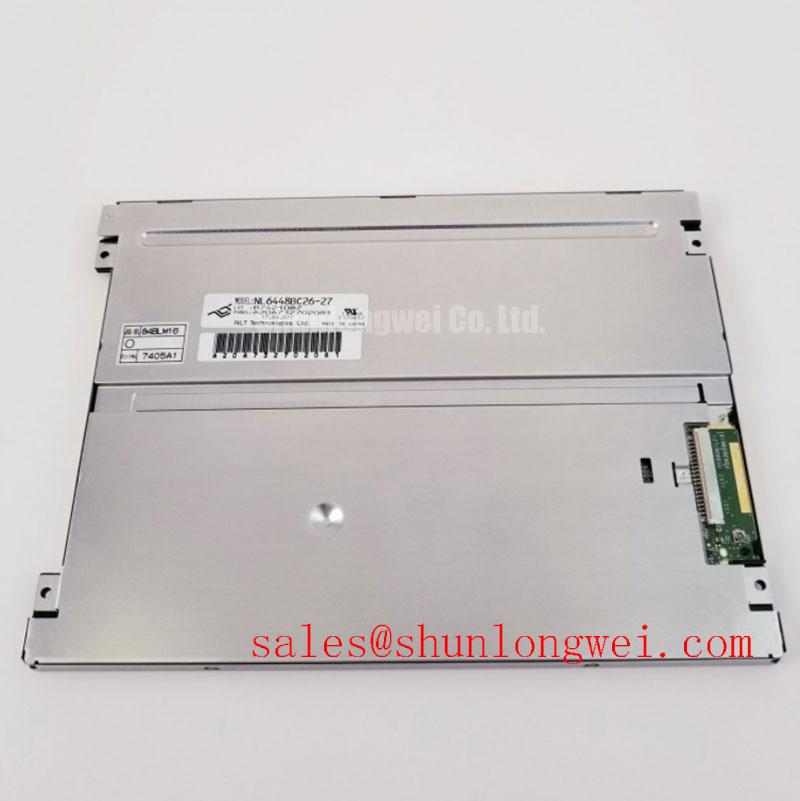
The supplied specification context does not confirm whether the NL6448BC26-27C uses a TTL or LVDS input, nor does it define JEIDA or VESA bit mapping, pixel clock limits, transmitter jitter tolerance, data hold time, connector pinout, or logic-level requirements. These details are essential to a reliable replacement assessment. The system integrator should verify the interface from the original panel documentation and controller schematic instead of applying a generic LVDS or TTL wiring assumption.
For LVDS systems, the engineering review should check differential-pair polarity, lane order, clock assignment, data-format mapping, termination practice, and cable shielding. For TTL systems, the review should address single-ended signal reference, bit order, clock phase, enable timing, and return-current paths. In either case, the layout objective is to preserve signal integrity through the complete cable and connector path. An oscilloscope or suitable protocol test fixture can compare the suspected panel path with a known-good path when image instability is reported.
Temperature changes can alter cable behavior, connector contact quality, oscillator timing, and panel response. A display that shows a clean static image but fails during moving graphics should be tested with the controller’s timing configuration recorded. Do not change several timing variables at once, because that removes the ability to identify whether the issue follows the panel, cable, controller, or configuration.
💡 Pro Tip: Keep differential display pairs routed as a controlled, closely coupled path with matched geometry, while allowing the system engineer to determine the final stack-up and timing margins through signal testing.
In a broader industrial TFT selection review, the The Ultimate Guide to Industrial TFT Technology provides useful background for comparing optical, interface, and integration factors. It should supplement, not replace, the NEC documentation for this exact model.
Optical Luminance Degradation Curve & CCFL-to-LED Modernization Retrofit Pathways
Before planning a backlight retrofit, identify the installed illumination architecture from the original panel documentation and equipment wiring. The supplied factory context does not confirm CCFL tubes, LED arrays, cold-ignition voltage, constant-current requirements, PWM dimming capability, luminance rating, half-life, or MTBF for the NL6448BC26-27C. Values such as 1500 to 1650 Vrms, 1000:1 dimming, and more than 50,000 hours must not be assigned to this model without a traceable manufacturer specification.
A CCFL system and an LED retrofit differ in more than the light source. The inverter, cable insulation, grounding arrangement, brightness control, thermal path, mechanical clearances, and electromagnetic behavior may all change. If the original module uses a high-voltage backlight, measure and isolate the backlight circuit according to the equipment service procedure. Do not connect an LED constant-current driver to an unidentified panel connector.
For a proposed LED modernization, the integrator should verify the LED string voltage range, regulated current, enable logic, dimming method, connector pinout, optical coupling, and heat dissipation. PWM frequency selection is system dependent. The design objective is to avoid visible modulation, camera interaction, audible artifacts, and control-loop instability while remaining within the panel’s documented backlight limits. Any claimed flicker performance requires measurement with an appropriate photometric or electrical test method.
Brightness assessment should use the same image pattern, measurement position, ambient lighting, and brightness command for each comparison. A single visual observation cannot establish a degradation curve. If maintenance records are available, plot readings over time and identify the measurement conditions. Without authoritative life-test data for this specific model and backlight assembly, no guaranteed operating-hour figure or half-life prediction should be published.
Acoustic noise during a retrofit may originate from the driver, transformer, inductor, mounting structure, or enclosure resonance. Check the driver independently, then reinstall it using the intended mechanical arrangement and repeat the test. EMC behavior belongs to the complete equipment and wiring installation; the display module or replacement driver should not be represented as independently certified for a finished machine.
For a related sourcing review involving a different display and backlight topology, engineers may examine NL10276BC30-24D. Compatibility still requires confirmation of dimensions, connector definitions, timing, optical performance, and backlight control. The NEC NL6448BC26-27C remains a TFT-LCD Display Module whose final suitability depends on matching the original equipment documentation and verified system interfaces.
⚠️ Field Alert: Disconnect equipment power and wait for the approved discharge interval before removing the display cable or inspecting any backlight wiring.