



Content last revised on September 10, 2026
Industrial EMI Noise Investigation, Chassis Shielding Continuity & Common-Mode Ferrite Chokes
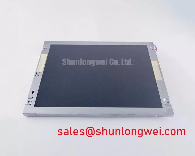
Begin incoming inspection by checking the NEC NL6448BC26-15 model marking, examining the TFT-LCD module for frame distortion or connector damage, and recording the panel condition before applying power.
The NL6448BC26-15 is an NEC industrial grade LCD/HMI panel supplied as a TFT-LCD display module. For equipment repair teams, correct identification is essential because display modules with similar mechanical formats can differ in interface mapping, supply requirements, backlight control, and connector orientation. The factory information available for this product confirms the manufacturer, product category, module construction, and official specification status. Electrical and optical values not stated in the available factory data should be checked against the original NEC documentation and the host equipment service record before integration.
| Item | Verified information | Engineering handling |
|---|---|---|
| Model | NL6448BC26-15 | Match the complete model suffix before ordering or installation. |
| Manufacturer | NEC | Use the original panel documentation for pinout and operating limits. |
| Product category | Industrial Grade LCD/HMI Panel | Evaluate it as a display module within the complete HMI assembly. |
| Construction | TFT-LCD Display Module | Confirm the host controller, backlight circuit, and mounting arrangement. |
| Specification status | Official Factory Spec Verified | Do not substitute unconfirmed interface or voltage data during repair. |
For a telematics display installed in a heavy mining shovel or earthmoving equipment cabin, begin the signal investigation at the complete cable path rather than at the panel alone. Inspect the controller connector, flexible cable seating, chassis entry point, and shield termination for looseness, contamination, or an unintended gap in the return path. Pixel jitter, intermittent horizontal bands, or unstable image content can be associated with signal integrity, grounding, power quality, or controller timing. These symptoms should be compared with a known-good display path before assigning a single cause.
A Design Consideration for high-noise equipment is to preserve a continuous shield reference around the display signal cable wherever the system architecture supports it. A shield that is bonded at one end but left mechanically floating at the display entry can behave differently from the original installation. The system designer should determine the correct bonding arrangement after reviewing the equipment grounding scheme, cabinet construction, and applicable safety requirements. The display module itself should not be represented as independently compliant with whole-machine EMC standards.
Common-mode ferrite suppression may be evaluated when unwanted common-mode energy is present on the display cable. Selection depends on the cable construction, signal spectrum, connector arrangement, and the effect of the component on the required differential signal. Adding a ferrite without checking the signal waveform can create an apparent improvement at one operating point while reducing margin elsewhere. An oscilloscope comparison at the controller output and panel input is a practical way to identify whether the disturbance is introduced along the cable path.
For differential routing, the integrator should follow the controller and cable documentation for characteristic impedance, pair balance, and allowable skew. The commonly used impedance target in an LVDS system is a system-level design value, not an automatically confirmed specification of the NL6448BC26-15. The original panel documentation should be used to confirm whether the replacement requires LVDS, another interface family, or a specific cable arrangement. Cable length, bend position, shield termination, and proximity to variable-frequency motor wiring should be reviewed together.
When the panel is used in a sealed operator display, chassis continuity also affects electrostatic discharge behavior. Keep exposed conductive surfaces, mounting hardware, cable shields, and the equipment reference at the potential defined by the system design. Any insulation, gasket, or painted bracket introduced during a retrofit should be checked so that it does not unintentionally interrupt the intended reference path.
VESA vs. JEIDA Data Mapping Alignment & Even/Odd Channel Signal Integrity
Before powering the replacement panel, compare the original controller board documentation with the panel interface record. Do not assume that a connector with the same pitch or apparent pin count has the same data mapping. JEIDA and VESA conventions can place color bits differently, and an incorrect even or odd channel arrangement may produce incorrect colors, split-screen behavior, missing image sections, or unstable synchronization. These observations can also result from a loose cable or unsuitable controller timing, so the inspection should include both electrical continuity and configuration data.
The required logic supply voltage for this model is not stated in the structured factory information supplied for this page. The system integrator should verify the required supply voltage from the original panel documentation. The same rule applies to enable signals, reset behavior, backlight supply, dimming input, and connector pin assignment. Do not apply a choice between possible voltage levels without documented confirmation.
Power sequencing should be checked with the panel disconnected first and then with the complete display assembly under controlled conditions. Record the order in which logic power, panel enable, video data, and backlight control become active. A white screen, delayed image, residual image after shutdown, or repeated restart can reflect timing interaction between the controller and the display module. The corrective value must be determined from the panel documentation and the host system timing rather than from a generic timing prescription.
For a field replacement, the best procedure is to photograph the original connector orientation, label both cable ends, and compare the replacement cable keying before insertion. Inspect contacts under magnification if the display has been exposed to vibration, dust, or repeated service work. The flexible cable should enter squarely and remain free from twisting at the locking mechanism.
Backlight operation also requires documentation review. The available factory data for this product does not confirm a backlight technology, rated brightness, dimming frequency, or service-life curve. If the host uses constant-current LED control, the integrator should verify current regulation, enable polarity, dimming method, and thermal conditions from the original display assembly. Claims such as a specific brightness-retention period or MTBF should not be assigned without a manufacturer test source.
For substitution research, engineers can compare the mechanical and electrical records of the NL10276BC16-06, but compatibility must be established through documented dimensions, connector details, signal mapping, and power requirements. A similar display category alone is not sufficient evidence of a direct replacement.
Thermal Dissipation, Display Integration & Light Guide Preservation
Thermal inspection is most useful after the panel has reached a stable operating condition inside its actual enclosure. Check whether the display frame is pressed against a heat source, whether the rear cover blocks intended ventilation, and whether the backlight driver transfers heat into the panel mounting structure. Localized heating near an edge can be caused by the driver, wiring, enclosure geometry, or mechanical pressure. Infrared readings should be interpreted alongside ambient temperature, camera emissivity settings, and the known-good assembly.
The factory information supplied here does not confirm the NL6448BC26-15 optical stack, light guide material, brightness rating, LED rail arrangement, or thermal limits. Avoid assigning an internal material or optical construction that is not documented. When a heat spreader or conductive rail is considered, the design team should verify electrical isolation, frame flatness, screw loading, clearance to the active area, and the effect on the original thermal path.
Cold-start evaluation should be performed gradually and with the panel protected from condensation. At low ambient temperature, liquid-crystal response can change and moving graphics may appear less fluid even when the video interface remains stable. This is a system-level behavior requiring verification against the equipment operating envelope. If a heater is used in the host design, its control method, sensor position, warm-up sequence, and condensation strategy should be validated by the equipment engineer.
Long-duration HMI screens deserve a separate review when the same status page remains visible for extended periods. Use the host software’s screen refresh, dimming, or page rotation functions only after confirming that they are acceptable for the operator interface. Persistent image retention can involve panel condition, drive settings, temperature, and operating history. It should be evaluated through controlled comparison rather than treated as proof of one specific internal failure.
FPC and cable handling are equally important during thermal and mechanical integration. The flex should follow the original bend path, avoid sharp frame edges, and remain free from tension when the enclosure is closed. Repeated opening of an equipment door can transfer force into the connector if the cable has no strain relief. A repair record should note the cable route, clamp position, connector lock condition, and whether the panel sits flat in the bezel.
⚠️ Field Alert: Disconnect power before inserting or removing the display cable, and confirm that the flexible cable is fully square before closing its connector lock.
For a broader enclosure and HMI integration review, see the Industrial Display & HMI Solutions reference area. It can help structure checks for environmental sealing, mounting, grounding, and service access without treating those system requirements as factory specifications of this NEC module.
Full-Screen Primary Color Inspection: Stuck Sub-Pixels & Background Uniformity Audit
Incoming inspection should use full-screen red, green, blue, black, and white test images at a controlled viewing distance. Observe the active area for permanently bright points, dark points, color contamination, line defects, uneven luminance, and areas that change when the cable is gently stabilized without applying pressure to the panel. Record the location of each observation on a panel map so that a later comparison can distinguish a repeatable display defect from a controller or cable issue.
A simple three-stage bench sequence is effective. First, display a dark field to reveal bright sub-pixels, edge leakage, and localized illumination irregularities. Second, display each primary color separately to identify pixels that fail to follow the commanded color. Third, display a white field and neutral test patterns to inspect broad uniformity, vertical or horizontal banding, and image stability. Acceptance limits must come from the purchasing specification or the original equipment quality standard; they should not be invented from a general LCD rule.
A 45-degree flashlight inspection can be used with power removed to examine the surface, bezel, connector region, and visible cable path for shadows, dents, contamination, or mechanical interference. It is a screening method, not proof of an internal construction fault. If a line or region appears only after flex movement, compare the panel with a known-good cable and controller, then use magnified visual inspection and signal measurement to isolate the affected section.
Backlight uniformity should be assessed separately from pixel performance. A dark patch that remains in the same physical location may require comparison with the backlight driver, diffuser assembly, and enclosure pressure. A pattern that follows the video content may instead require investigation of mapping, timing, or signal integrity. Keep these observations separate in the inspection report.
If the host system uses PWM dimming, verify the controller’s documented frequency range, duty-cycle behavior, enable polarity, and minimum stable brightness before connecting the replacement. The supplied factory information does not confirm a PWM specification for this model. Visual flicker, audible driver noise, or unstable low-brightness operation should be checked with suitable optical and electrical instruments rather than assigned to the panel without evidence.
After the screen test, repeat the inspection during power cycling and after the equipment reaches its normal operating condition. Check whether the image appears consistently, whether shutdown leaves residual content, and whether the connector remains mechanically secure after enclosure closure. Archive the test image set, photographs, measured supply behavior, and panel identification with the repair record.