



Content last revised on September 22, 2026
NL6448BC33-64E Industrial LCD Module Overview
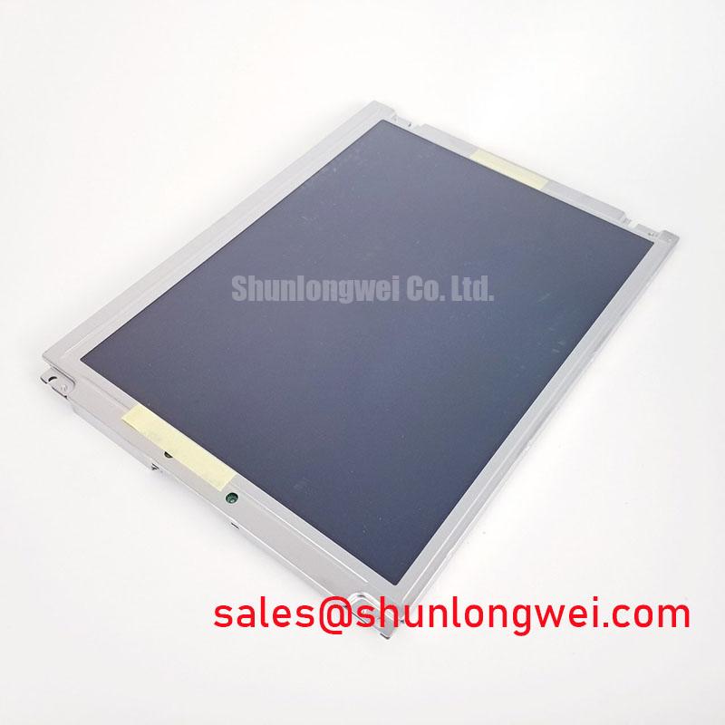
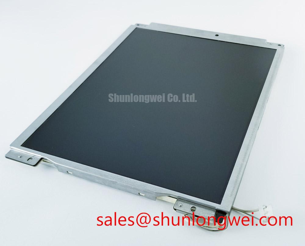
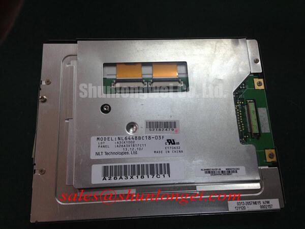
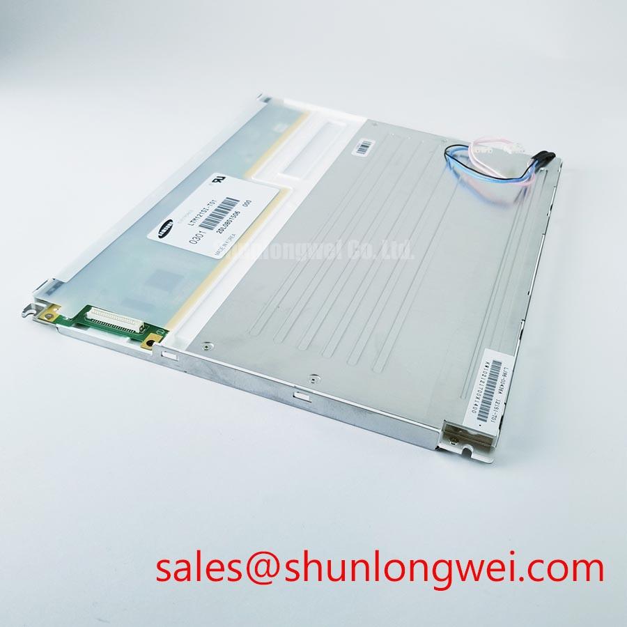
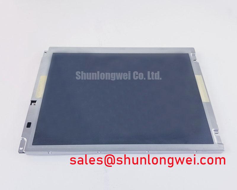
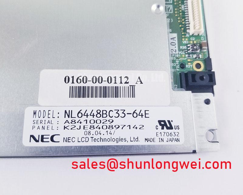
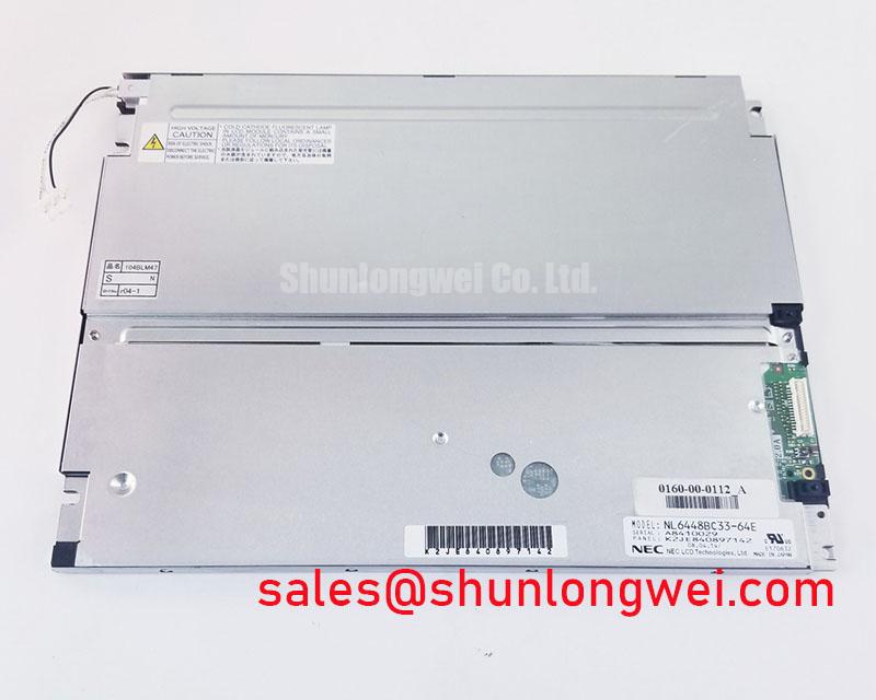
With power removed, inspect the NL6448BC33-64E display perimeter, mounting points, connector seating, and front optical surface before reconnecting a failed industrial HMI terminal. This NEC unit is identified as an Industrial Grade LCD/HMI Panel in a TFT-LCD Display Module enclosure. The verified factory information confirms the product category and manufacturer; the system integrator should verify all electrical, timing, connector, mechanical-outline, and optical requirements against the original equipment documentation before installation.
| Item | Verified Information |
|---|---|
| Model | NL6448BC33-64E |
| Manufacturer | NEC |
| Product Category | Industrial Grade LCD/HMI Panel |
| Module Type | TFT-LCD Display Module |
| Specification Status | Official Factory Spec Verified |
For repair work on a protection relay terminal or SCADA dispatch console, matching the visible screen size alone is not enough. The replacement decision should begin with the equipment’s original panel label, display controller documentation, cable arrangement, mechanical drawing, and power architecture. A panel can appear mechanically similar while requiring a different signal interface, backlight supply arrangement, mounting pattern, or initialization sequence.
Industrial Bezel Mechanical Envelope Tolerances & Mounting Screw Torque Optimization
Before fitting the NEC NL6448BC33-64E into an industrial bezel, place the inactive module into the chassis without tightening fasteners. Check that the frame sits flat, that no cable is trapped behind the rear housing, and that the bezel does not apply force to the active display area. Uneven compression can create pressure-related optical irregularities that are most noticeable on a dark screen, a gray diagnostic page, or a uniform white field.
The available verified product data identifies this unit as a TFT-LCD display module but does not establish a factory mounting torque, outer bezel tolerance, front-surface treatment, sunlight contrast rating, or optical coating specification. These details must not be inferred from another NEC panel or from a visually similar display. The installer should use the original equipment mechanical drawing and its approved fastening procedure.
Field Alert: Disconnect system power and allow stored energy to discharge before inserting or removing the panel cable, because connector contact during an energized state can expose signal pins to unwanted voltage levels.
As a Design Consideration, use a progressive cross-pattern tightening method when the host enclosure uses multiple mounting points. This approach helps keep load distribution even while the installer checks for bezel distortion and verifies that the panel face remains free from localized pressure. The final tightening limit must be determined by the equipment maker’s enclosure design, the fastener type, and the original mounting hardware.
For equipment refresh planning, engineers sometimes compare footprint class, display geometry, interface documentation, and mechanical drawings against related industrial panels. The NL10276BC16-06 can be reviewed as a separate reference model during documentation-based comparison, but it should not be treated as a direct replacement without validating all system-level requirements.
Polarizer Durability & Optical Retardation Film Inspection under Direct Industrial Lighting
When a control-room operator reports a washed-out image, first separate front-surface visibility from image-generation failure. Clean only by the procedure approved for the installed equipment, then inspect the panel while displaying stable black, white, gray, red, green, and blue test fields. Look for changes that move with viewing angle, remain fixed in the same screen location, or become more obvious under oblique industrial lighting. These observations help determine whether the symptom is related to the display surface, panel mechanics, signal data, or the backlight path.
The official verified information for NL6448BC33-64E does not state a polarizer type, anti-glare treatment, anti-reflective coating, viewing-angle specification, contrast ratio, or backlight life rating. It would therefore be inaccurate to assign TN, IPS, MVA, anti-glare, or sunlight-readability properties to this exact NEC model without the original factory datasheet. Direct-light performance should be evaluated on the actual installed panel and under the illumination conditions of the host cabinet or console.
Industrial display surfaces can show reflections from overhead lighting, window light, status lamps, and nearby operators’ equipment. As an Engineering Recommendation, evaluate readability with the normal operator viewing position, the actual enclosure window, and the intended ambient lighting condition. If the image is legible with a temporary shade but weak under direct light, the finding may point to a system visibility issue rather than a confirmed logic-board failure.
Backlight brightness changes should also be assessed carefully. A dim image can originate from the panel’s illumination assembly, a power source, a control signal, wiring resistance, or a protection response in the host driver. No LED backlight lifetime, brightness-retention curve, dimming frequency, or current-driver characteristic is confirmed for this model in the available factory data. The system integrator should verify the required backlight connection and supply conditions from the original panel documentation.
Where a maintenance team is reviewing related NEC display options within a broader display topology, the NL10276BC30-24D may be documented alongside the installed panel. That comparison should remain limited to verified drawings and electrical documentation rather than visual similarity or assumed backlight compatibility.
High-Humidity Storage Margins (60°C / 90% RH) & Delamination Prevention Protocols
Before returning an out-of-service display to a cabinet, inspect the module edge, front surface, rear housing, and connector region for moisture residue, corrosion signs, contaminants, or mechanical stress. If the panel has been stored in an uncontrolled environment, allow it to stabilize according to the host equipment’s approved service process before power is applied. Do not use an assumed humidity or thermal-cycle rating for the NL6448BC33-64E unless it is shown in the original NEC documentation.
The verified factory description confirms an industrial TFT-LCD module, but it does not provide a storage humidity rating, operating temperature range, low-temperature response specification, thermal-cycle limit, edge-seal construction, or delamination qualification. Statements about a specific high-humidity margin, sub-zero response behavior, perimeter sealing method, or liquid-crystal transition performance would not be official specifications for this part.
As a Design Consideration, condensation control matters whenever a display is moved between storage, transport, outdoor service access areas, and a conditioned control room. Moisture can affect connectors, cable interfaces, enclosure windows, and surrounding electronics even when the display itself appears clean. The maintenance team should inspect the complete display assembly, including the host controller board and backlight wiring, rather than limiting the examination to the front glass.
If a screen appears slow, uneven, or intermittent after exposure to a temperature change, record the condition at power-up and after the equipment reaches its normal internal operating state. Compare the observed image with a known-good console where available. This method avoids treating one visible symptom as proof of a single panel defect. Signal quality, supply stability, backlight behavior, connector contact, and panel optical response can each require separate verification.
For a broader explanation of industrial TFT display interfaces, integration factors, and common evaluation mistakes, consult The Ultimate Guide to Industrial TFT LCD Technology. The guide supports general engineering review but does not replace the original documentation required for this NEC model.
Flashlight Dark-Shadow Optical Diagnostic to Isolate Logic vs. Backlight Failure Modes
For a black-screen complaint, begin with the equipment energized only after all connection checks are complete and safe service conditions have been established. Set the host system to generate a known display state, then observe the panel from the normal viewing angle. A flashlight directed across the inactive-looking screen at an oblique angle can sometimes reveal a faint underlying image. If an image is visible under external illumination, the result can support further investigation of the backlight power path, illumination control, and associated wiring. It does not independently prove the exact failed part.
Use controlled color and grayscale images where the host system permits them. A stable white image can help reveal brightness nonuniformity. Red, green, and blue fields can help identify whether a defect follows a specific image color or remains fixed regardless of the displayed data. Gray fields are useful for finding pressure marks, line artifacts, intermittent pixel regions, or weak illumination zones. Document the test image, viewing angle, cable position, and power state so later troubleshooting does not depend on memory alone.
If there is no visible image with either normal viewing or the flashlight test, verify the host controller output and the panel connection before assigning responsibility to the LCD module. The available verified factory information does not specify whether NL6448BC33-64E uses TTL, LVDS, or another interface, and it does not provide clock, jitter, data hold, impedance, or power-sequencing values. The system integrator should verify the required interface definition from the original panel documentation and compare the host signal path with a known-good installation using appropriate test equipment.
In electrically noisy industrial environments, a display symptom can be intermittent because of cable routing, grounding arrangement, connector retention, supply disturbance, or controller behavior. Design Consideration: keep display signal routing and power routing consistent with the original equipment layout, particularly where switching equipment, servo drives, relays, or high-energy conductors are present. Any EMC assessment belongs to the complete equipment assembly; this individual TFT-LCD module should not be represented as independently compliant with system-level EMC standards.
For a high-voltage substation protection terminal or SCADA dispatch console, the practical service sequence is to confirm the original panel model, inspect the mechanical fit, verify the cable and host power path, run controlled image tests, and only then evaluate the NL6448BC33-64E as the replacement display module. This preserves traceability and helps the repair team distinguish display-side observations from faults originating elsewhere in the console.