

Content last revised on October 17, 2026
Incoming Benchtop Inspection: COG/TAB and ACF Integrity
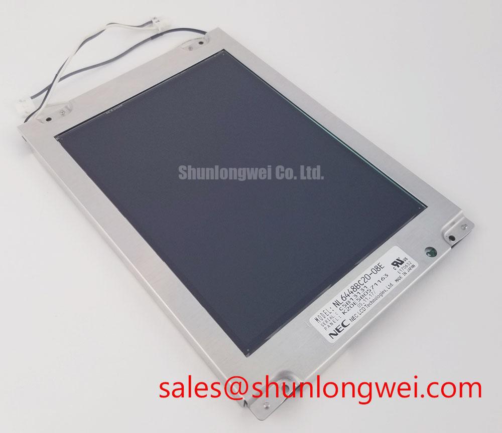
Start incoming inspection with the display disconnected from the instrument and protected from static discharge, then examine the active area, perimeter seal, flexible cable, and connector seating under controlled bench lighting. The NEC NL6448BC33-27 is identified as a TFT-LCD active matrix color display module for industrial HMI use; the replacement review should therefore begin with physical and interface compatibility rather than with a visual brightness comparison alone.
For a field screen showing missing color bands, intermittent rows, or localized image loss, run a controlled primary-color sequence using red, green, blue, white, and black test fields. Observe whether the defect remains fixed on the glass, follows a cable movement, or changes with the display operating state. A 45-degree flashlight inspection across a black image can help separate uneven illumination from a line defect associated with the panel edge or driver bonding area. This is a diagnostic observation method, not a model-specific failure threshold.
COG, TAB, and ACF areas require non-invasive handling. Do not press the visible panel edge or flex the bonded region to provoke a fault. A temporary response to pressure may point toward an interconnect or bonding issue, but it does not establish a single root cause. Compare the suspect unit with a known-good signal path and record the exact location, color dependency, and repeatability of the artifact.
Cold testing needs a separate record. Liquid crystal viscosity can increase at sub-zero temperatures, extending gray-to-gray transitions and making moving text or waveform traces appear smeared. If the instrument uses a heater or controlled enclosure, evaluate its control sequence as part of the system rather than assuming that a warmer panel alone resolves the symptom. The integrator should verify the original panel documentation for supply voltage, backlight method, timing, and temperature limits before authorizing a replacement.
Edge-Lit Backlight Thermal Review and Optical Preservation
Inspect the narrow display edges for concentrated heat, restricted ventilation, and mechanical contact with the instrument bezel. A thermal review should consider the complete backlight assembly, its driver, the enclosure, and the optical stack. Verify the backlight construction, light-guide material, and factory brightness rating for NL6448BC33-27 in the original panel documentation.
Where an edge-lit arrangement is present in the original equipment, designers should evaluate whether an aluminum spreader or equivalent thermal path can distribute local heat without stressing the panel frame. This is a Design Consideration, not a factory specification for this model. Avoid adding pressure against the optical stack, and preserve the original bezel clearance so that thermal expansion does not create localized bright spots or shadowing.
Signal integrity must be checked at the actual display connector. Confirm whether the host uses TTL or LVDS, then match the transmitter format, pixel order, clock polarity, and data mapping to the original panel documentation. For LVDS interfaces, JEIDA and VESA mapping differences can produce incorrect colors even when the image appears stable. Differential pairs should follow a controlled, symmetrical routing strategy, with return paths kept continuous and unnecessary connector transitions avoided.
Clock jitter and data setup and hold margins should be checked across the intended industrial temperature range with an oscilloscope at the receiving interface. The acceptable margin depends on the panel timing requirements, cable construction, transmitter capability, and enclosure environment. 💡 Pro Tip: For an LVDS connection, control skew within each differential pair and between data and clock pairs according to the interface requirements to reduce the risk of intermittent color or line errors.
For a hardware replacement review, compare the connector position, cable exit direction, active-area geometry, mounting reference points, optical viewing requirements, and electrical interface before considering the NL6448BC33-71. A similar diagonal size or resolution alone does not establish a drop-in replacement.
Temperature Screening and Sub-Zero Liquid Crystal Response
Thermal cycling should focus on image response, seal condition, cable stress, and frame alignment as separate observations. At low ambient temperature, increased liquid-crystal viscosity can lengthen gray-to-gray transitions, particularly in rapidly changing test traces, scrolling measurement data, and dark-to-light patterns. Record the time-dependent visual response during cold start and again after thermal stabilization rather than judging the panel from a single frame.
The stated model identity does not by itself authorize a specific operating temperature range. Use the original NEC documentation and the instrument manufacturer’s environmental specification to establish the allowed window. If the application includes a controlled heater, verify its power sequencing, sensor location, and fault behavior. Operate the display only within the conditions required by the approved operating profile.
At the warm end of the cycle, inspect for frame distortion, uneven luminance, seal-edge changes, and connector movement. Perimeter sealant and optical layers respond differently to thermal expansion, so a bezel that is acceptable at room temperature may apply unwanted stress during cycling. Mounting features should allow the panel to sit flat without bending the glass or compressing the flexible cable.
Direct sunlight testing also needs a defined optical method. Evaluate contrast, reflections, viewing angle, and anti-glare behavior with the final cover window and bezel installed. A panel that appears clear on an open bench may lose measurement readability behind a tinted window or under oblique illumination. The broader principles for enclosure sealing, display mounting, and industrial HMI environmental design are discussed in the Industrial Display & HMI Solutions engineering resource.
Backlight Drive and Secondary Insulation Assessment
Do not infer the backlight drive architecture from the LCD model number. Before applying power, identify the original backlight connector, driver topology, enable signal, dimming method, and shutdown behavior from the equipment documentation. A CCFL assembly and an LED assembly require different driver, insulation, and measurement procedures; substituting one assumption for the other can damage the panel or produce misleading brightness results.
For equipment using a high-voltage cold-cathode backlight, secondary insulation should be inspected with the assembly isolated from the logic electronics. The test voltage, ramp rate, leakage limit, probe category, and discharge procedure must come from the approved service method and applicable safety requirements. Acoustic noise during ignition can also be influenced by the inverter, mounting surfaces, wiring, and enclosure resonance, so it should be evaluated at system level rather than assigned automatically to the LCD module.
For an LED backlight, verify constant-current regulation, enable timing, dimming polarity, and thermal behavior under the original optical load. PWM dimming performance depends on the driver and control interface; a claimed dimming ratio cannot be assigned to this model without a corresponding factory specification. Brightness retention or half-life is likewise a system and source-data matter involving drive current, temperature, optical construction, and duty cycle. Do not present an MTBF or operating-hour figure as a guaranteed property of the display without an applicable manufacturer document.
Power sequencing deserves attention during replacement. The host should bring logic supply, control signals, video data, and backlight drive into the order required by the original interface, then remove them without leaving a residual image or an unintended illuminated state. Flexible cable insertion must be performed with power removed, and the connector lock should be fully engaged before the panel is returned to the instrument. For precision electronic test and measurement instruments, verify the final image with static screens, moving traces, grayscale transitions, and the actual front-panel window installed.