

Content last revised on September 10, 2026
Diagnosing Backlight and Illumination Problems
Begin a dim-image investigation by separating image generation from illumination. In a controlled, low-ambient-light bench check, power the original system through its approved service procedure and observe whether a faint image is present while the screen appears dark. A visible image under an oblique inspection light can indicate that the host is producing picture data while the illumination path, its supply, its control signal, or associated wiring needs further investigation. A fully blank image, unstable synchronization, or repeated restart behavior requires inspection of the host display path as well.
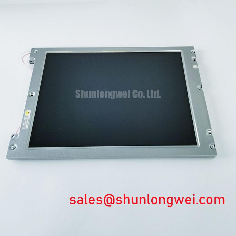
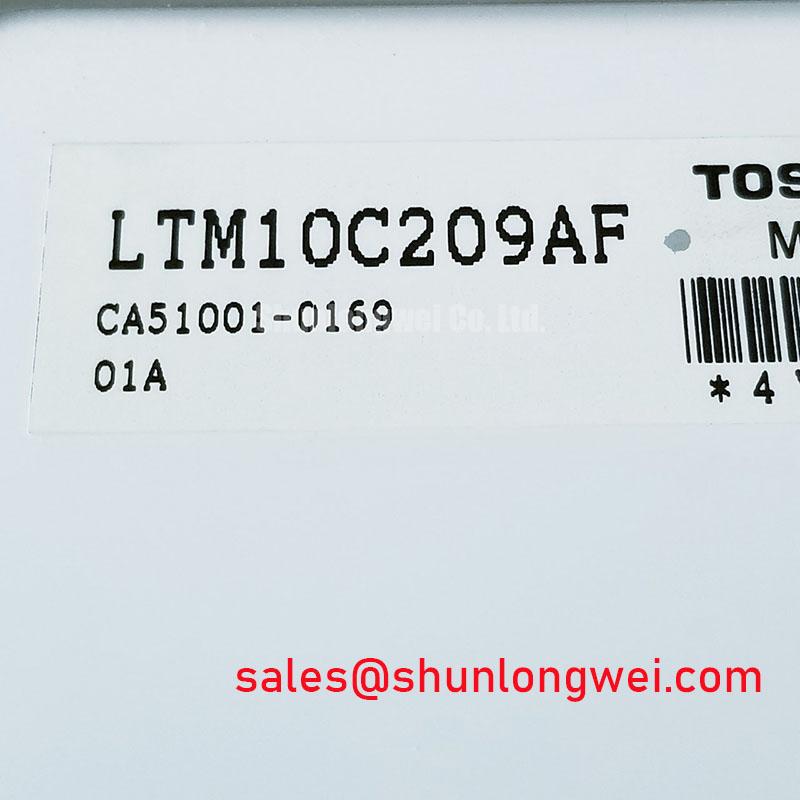
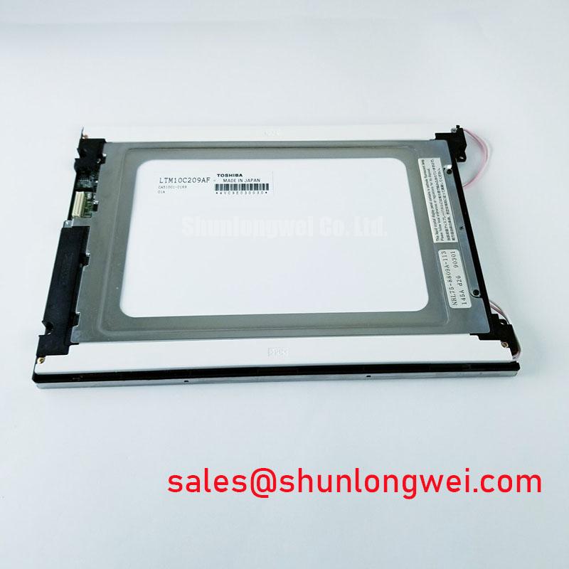
The official identification provided for the LTM10C209AF confirms its industrial TFT-LCD module category but does not confirm the original backlight technology, lamp ratings, LED-driver requirements, luminance value, or operating-life figure. A technician should therefore obtain the original panel and equipment documentation before treating a CCFL assembly or an LED conversion board as compatible with this exact model. High-voltage CCFL starting behavior, constant-current LED regulation, dimming polarity, enable logic, and mechanical fit are system-level conditions rather than published specifications in the provided factory data.
Where a machine owner is assessing an illumination modernization, the practical task is to preserve the original display timing and to validate the replacement illumination assembly separately. The host transmitter must retain adequate clock stability and data timing at the actual equipment temperature range; these margins are determined by the panel interface documentation and must be verified with measurements on the installed signal path. Any audible noise, cyclic brightness change, or image disturbance during dimming should be tested at the original control input before the display module is blamed.
⚠️ Field Alert: Disconnect and reconnect panel and backlight cables only after the equipment is fully de-energized, because live insertion can expose signal and power contacts to unintended voltage transitions.
For a broader service reference when comparing industrial TFT display behavior, interface checks, and illumination symptoms, consult The Ultimate Guide to Industrial TFT LCD Technology. This reference supports evaluation work but does not replace the original LTM10C209AF documentation or the machine manufacturer’s service requirements.
Display Interface and Logic Power-Rail Verification
A replacement panel should never be connected on the assumption that the model designation alone establishes its logic supply or signal format. The factory information supplied here does not state whether the LTM10C209AF requires a particular logic voltage, whether its host connection is TTL RGB or LVDS, what color-data mapping it uses, or what sequence is required between logic power, video data, and illumination enable. The system integrator should verify the required supply voltage, interface type, pin assignment, and power sequence from the original panel documentation.
On a machine with split regions, incorrect colors, repeated vertical patterns, or a display that lights without rendering a stable image, inspect the mating connector for uneven insertion, oxidation, bent contacts, cable tension, and damage around the controller-board connector. Then compare the observed signals against a known-good machine or the documented host timing. These symptoms can arise from several points in the chain, including cable integrity, host controller configuration, power stability, or a panel interface mismatch; they should not be assigned to one cause without measurement.
Design Consideration: preserve the intended signal-return path and controlled routing characteristics between the host board and the module, especially where switching supplies, contactors, or long cable runs create electrical noise. Signal integrity should be assessed at the panel-side connector with suitable instrumentation while the machine runs through its relevant operating states. The general concepts behind filtering conducted interference are described in this line filter reference; it is contextual information rather than a certification or compliance statement for this LCD module.
For a hazardous petrochemical Zone 2 operator station, display integration remains subject to the complete enclosure, cable-entry, grounding, power architecture, and site safety assessment. The LTM10C209AF itself should be evaluated as a display replacement within that equipment system, not represented as an independently certified explosion-protection or EMC solution.
Full-Screen Primary-Color and Background-Uniformity Inspection
Use a controlled visual inspection before returning a repaired terminal to service. First, display a uniform red field, then a uniform green field, then a uniform blue field from a verified signal source. Observe the whole active image area from the normal operating position and from a slight angle, noting persistent bright points, dark points, lines, color shifts, localized shadows, or zones that change when the cable is moved. Record findings with the same test source and viewing conditions so that a replacement panel can be assessed against the same baseline.
After the three primary-color screens, use neutral gray and full white images to check for nonuniform illumination, edge shading, and intermittent image behavior. A flashlight examination at approximately 45 degrees can be useful when distinguishing a low-illumination condition from a missing image condition. It does not confirm a specific internal failure mechanism. If a line is present on every color field and remains unchanged after a documented cable and host-path check, the panel assembly warrants further evaluation. If the defect changes with cable position or equipment vibration, connector seating and cable strain relief should also remain in scope.
Do not infer a specific internal construction issue from a visual symptom alone. The provided official factory information establishes the module category and enclosure type, but it does not publish sub-pixel acceptance criteria, uniformity limits, driver construction, or repairability of internal panel elements. Procurement and maintenance teams can use the inspection record to determine whether the existing panel remains usable for the equipment’s visual task and whether a correctly documented replacement should be evaluated.
When assessing display behavior near powered control hardware, investigate the complete electrical environment. Common-mode and differential-mode disturbances can affect adjacent wiring differently, and the system-level distinction is outlined in the linked line-filter reference. Measurements should be made against the known-good signal path and the equipment’s documented grounding arrangement rather than applying a generic filter modification.
Investigating Temperature-Dependent Display Response During Cold Start
During a cold-start complaint, allow the operator station to reach its actual enclosure temperature and compare the screen response against the same unit after thermal stabilization. Slow transitions, temporary ghosting, or an image that appears to lag may be associated with temperature-dependent display behavior, but the observation must be separated from host CPU startup, video initialization, supply sequencing, and illumination control. The factory information available for the LTM10C209AF does not provide a gray-to-gray response specification, a low-temperature operating range, or thermal-cycle limits, so no numeric environmental rating should be assigned to this model from the supplied data.
Check whether the display issue occurs before the host provides stable video, only during the first minutes of operation, or throughout a complete operating cycle. Confirm that the panel cable is seated without tension and that the housing is not imposing twist or point loading on the TFT-LCD display module. Design Consideration: avoid forcing the panel enclosure during installation, because mechanical stress can complicate diagnosis and can change when the surrounding equipment expands or contracts with temperature.
The perimeter condition should be visually inspected for damage, contamination, or a gap created by the host enclosure, but internal seal materials and their temperature capability must not be assumed without the original manufacturer documentation. For equipment considered for industrial HMI or monitoring-panel service, including a Zone 2 hazardous-area operator station, the enclosure sealing, approved thermal conditions, and startup sequence are all system-determined and require validation by the equipment owner or qualified system engineer.
Where cold-start timing is under review, capture the host power rails, panel enable behavior, and video activity together. This establishes whether the panel receives valid conditions before an image is expected. Electrical behavior at semiconductor junctions is often discussed through concepts such as the depletion region, but that general physics reference does not establish any internal design, protection rating, or failure mechanism for the LTM10C209AF.