

Content last revised on September 10, 2026
LT084AC27500 Replacement and Backlight Interface Verification
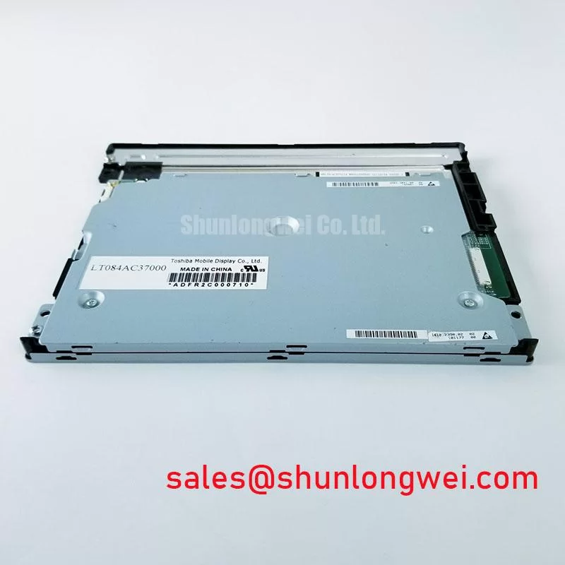
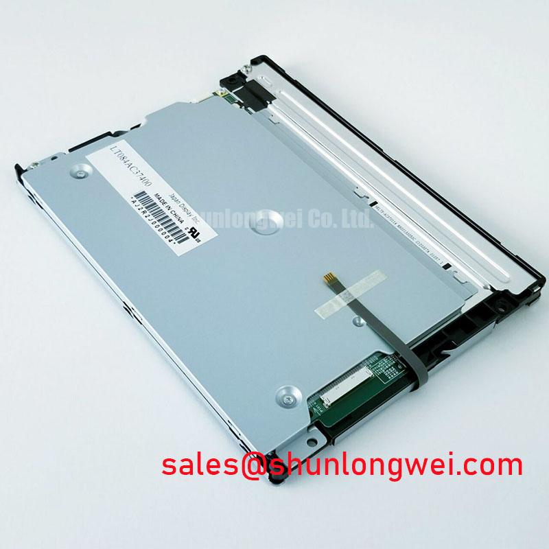
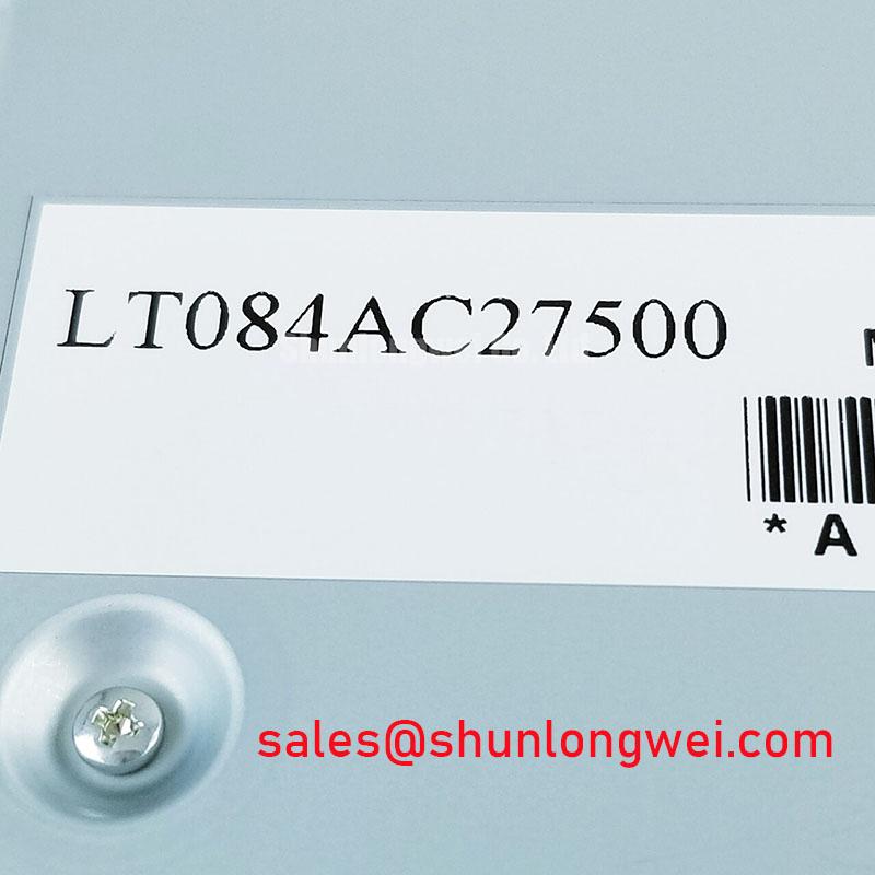
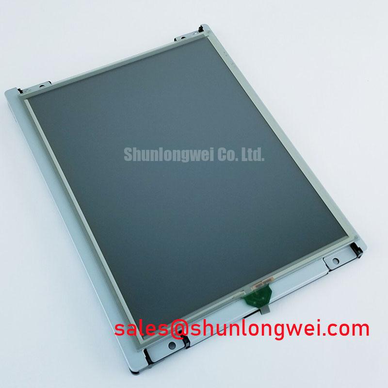
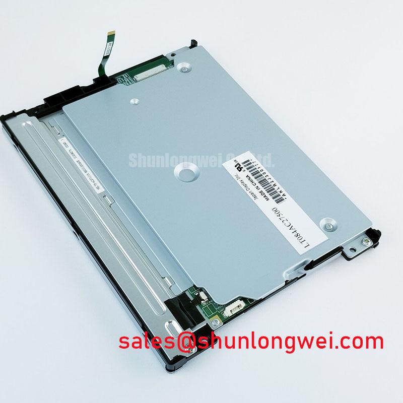
Before fitting LT084AC27500 into a replacement HMI assembly, compare the existing module label, mechanical outline, connector position, cable orientation, and host controller interface against the original panel documentation with power removed. This Toshiba unit is identified as an Industrial Grade LCD/HMI Panel supplied as a module; the available official factory information does not confirm the display resolution, active area, optical performance, interface type, supply rails, backlight architecture, or environmental ratings. Those items must be verified from the original equipment documentation before electrical connection.
| Item | Official Factory Specification |
|---|---|
| Model | LT084AC27500 |
| Manufacturer | Toshiba |
| Product Category | Industrial Grade LCD/HMI Panel |
| Package Form | Module |
| Specification Status | Identity and package form verified; detailed specifications not confirmed |
For repair evaluation, record the old display assembly part number, host board connector designation, cable part number, and any backlight driver markings. A physical fit alone does not establish electrical compatibility. Industrial display replacements require the system integrator to confirm the required supply voltage, video signalling standard, timing arrangement, control logic, and backlight connections from the original panel documentation.
Backlight and Dimming Interface Verification
The available official information for LT084AC27500 does not identify the backlight technology, dimming ratio, dimming method, lamp operating voltage, or expected brightness retention. Therefore, WLED operation, constant current driving, PWM dimming capability, CCFL compatibility, and lifetime figures must not be assumed for this model.
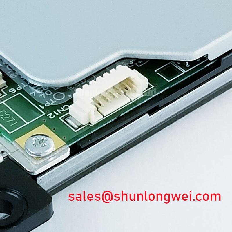
During a replacement assessment, isolate the display logic cable from the illumination connection where the equipment design permits, then identify whether the host system contains a separate inverter or a dedicated LED driver. A controller built around lamp ignition circuitry and a controller built around a current regulated LED channel have fundamentally different electrical interfaces. Connecting an unknown panel illumination port to an unverified driver can damage the panel or the host assembly.
Design Consideration: where an original system uses PWM brightness control, technicians should verify the polarity, control reference, enable state, and startup sequence with the known working display path. Visible flicker, intermittent illumination, or brightness instability can arise from several sources, including an incompatible control waveform, poor cable contact, power rail disturbance, or a driver protection response. Oscilloscope comparison with the original interface is more reliable than attributing the symptom to a single cause.
Pro Tip: Disconnect and reconnect display and illumination cables only after the equipment power source has been isolated and stored energy in the display power circuit has been allowed to discharge.
Thermal Expansion Clearance Sizing across Heavy Industrial Metal Enclosure Cutouts
Mechanical integration of LT084AC27500 should begin with a drawing based comparison rather than a bezel only comparison. The official information available here confirms module form but does not publish outer dimensions, mounting hole positions, bezel depth, fastening method, or allowable mounting torque. The enclosure cutout, gasket stack, mounting brackets, and cable bend space must therefore be checked against the original panel documentation and the removed assembly.
Design Consideration: a metal enclosure can transfer assembly stress into the display perimeter when the cutout is misaligned, the mounting surface is uneven, or clamp load is concentrated at one location. Such stress may be associated with pressure marks, local brightness variation, image distortion, or gradual mechanical damage. Use a flat mounting datum, retain clearance appropriate to the validated mechanical drawing, and tighten hardware progressively in a balanced cross pattern only where the equipment service instructions specify this method.
For equipment exposed to vibration, including potential telematics displays in heavy earthmoving machinery, evaluate the complete installation rather than the panel alone. The cable restraint, rear cover support, connector retention, enclosure sealing, and vibration path all affect replacement suitability. Engineers evaluating display service practice under demanding installations can use this Industrial Display & HMI Solutions reference as a broader maintenance and integration resource.
Do not infer a backlight lifetime, thermal cycle range, or optical durability figure for LT084AC27500 from general industrial display practice. Those values require a Toshiba source document or validated system level qualification evidence.
Cold-Start Display Response Evaluation during Machine Power-Up
The official factory information currently available for LT084AC27500 does not state gray to gray response time, operating temperature range, storage temperature range, liquid crystal behaviour at low temperature, or perimeter seal construction. No specific cold start performance claim can be assigned to this model without the original manufacturer documentation.
At low ambient temperature, liquid crystal displays can show slower visual transitions, reduced apparent contrast, or delayed image stabilization. These observations are system conditions to investigate, not a model specific specification. When an equipment display appears slow during startup, verify ambient temperature, panel supply stability, video timing, controller initialization order, and whether the same effect occurs on a known good display. A display controller that begins transmitting data before the panel is correctly powered or released from reset may create symptoms that resemble a panel fault.
Design Consideration: if the original host interface uses differential signalling, preserve the cable arrangement, shielding scheme, pair polarity, and connector pin assignment established by the equipment manufacturer. Differential pair routing and termination must be validated at system level to limit timing disturbance and common mode noise. The available official information does not confirm whether LT084AC27500 uses LVDS, TTL, JEIDA mapping, VESA mapping, or another interface arrangement.
For vehicles or machines with battery monitored startup systems, state of charge and state of health information can help maintenance teams distinguish a low energy supply event from a display interface issue. The industry definitions discussed in this state of charge reference are useful background, but they do not define the electrical requirements of this Toshiba display module.
EMI Investigation, Chassis Shielding Continuity and Common-Mode Ferrite Chokes
Investigate horizontal noise bands, pixel disturbance, intermittent image loss, or unstable synchronization by checking the full signal path: controller connector, display cable, grounding points, enclosure bonding, power return path, and nearby switching equipment. The official factory information does not provide electromagnetic compatibility ratings, shielding requirements, cable specifications, or immunity limits for LT084AC27500. It would be inappropriate to claim standalone EMC compliance for the module.
Design Consideration: maintain shielding continuity in accordance with the original equipment cable construction and chassis grounding design. A screened cable that is incorrectly terminated, pinched, or routed beside a noisy power conductor can couple interference into sensitive display signalling. Where common mode ferrites are already part of the validated equipment harness, retain their original position and orientation. Any added suppression component should be evaluated by the system engineer to confirm that it improves noise behaviour without compromising signal integrity or startup sequencing.
Variable frequency motor drives, switching supplies, and inductive loads can create conducted and radiated disturbances in an industrial enclosure. The general principle of transient energy control is described in this snubber circuit reference; it is background information for system level power design and is not an electrical specification or recommended circuit for LT084AC27500. For a replacement panel, verify image stability with the machine operating in its normal electrical states, then compare results against the known good signal path before changing cable routing, grounding, or controller hardware.