Content last revised on October 19, 2026
20-Pin/30-Pin Differential LVDS Timing, Pixel Clock and Skew Compensation
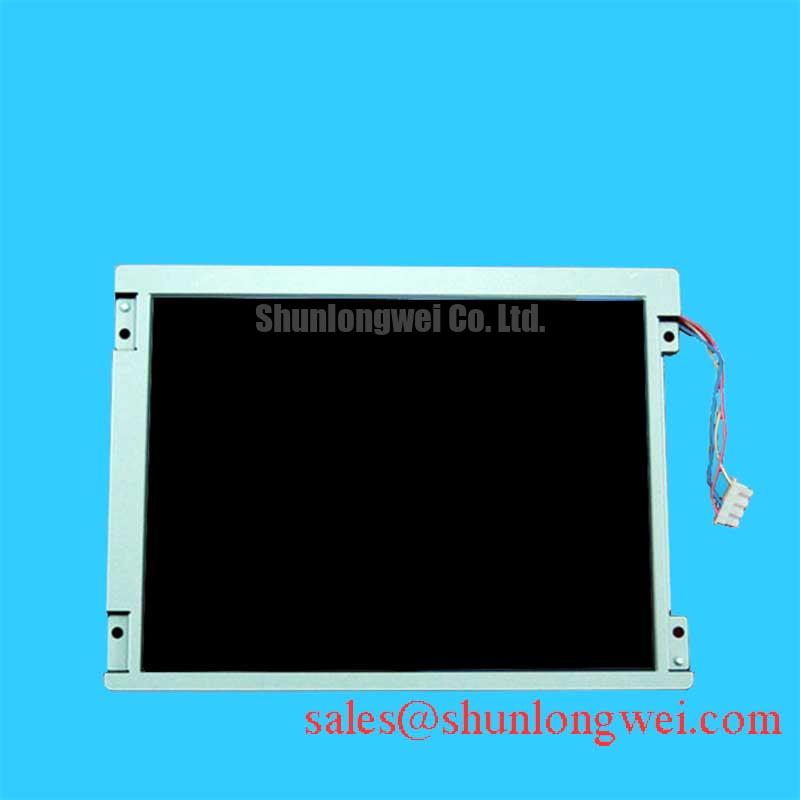
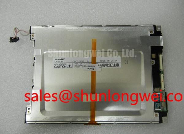
AA084VJ01 is identified in the supplied product data as a Mitsubishi Electric Industrial Grade LCD/HMI Panel using a TFT-LCD active matrix color display module construction. Its specification status is listed as Decoded Baseline / Standard Form Factor. The available product record does not assign a confirmed panel supply voltage, pixel resolution, viewing angle, luminance rating, connector pinout, or backlight rating, so those values should not be treated as fixed replacement criteria without the original panel documentation.
- Confirm the panel identity as AA084VJ01 and match the Mitsubishi Electric label with the service record.
- Inspect the display glass, bezel, connector area, and mounting points before applying power.
- Check the mating cable for straight insertion, clean contacts, and a fully engaged lock.
- Prepare an ESD-controlled bench before pixel, backlight, and interface testing.
Start interface diagnosis by identifying whether the host equipment uses a 20-pin or 30-pin display connection, then compare the cable keying, connector position, and signal assignment with the original service documentation. A physically compatible connector does not by itself confirm compatible LVDS mapping. The system integrator should verify the required supply voltage from the original panel documentation rather than assuming a 3.3 V or 5.0 V interface.
As a Design Consideration, the logic supply rise profile should be observed during power-up, with the host controller, display enable signal, and differential data activity checked on the same time base. The supplied engineering brief identifies a 0.5 ms to 10 ms power-on rise-time evaluation window, but this should be treated as an integration test condition rather than an AA084VJ01 factory rating. A supply that reaches its final level correctly can still produce a blank image if the enable sequence or reset timing is incompatible.
For LVDS routing, maintain controlled differential geometry and a continuous return path. A nominal 100 ohm differential routing target is a common Design Consideration for LVDS systems, subject to the transmitter, receiver, cable, and PCB stack-up requirements. Check the clock pair and data pairs for excessive skew, connector discontinuity, and unnecessary stubs. Split-screen images, repeated vertical bands, or unstable color blocks can indicate mapping, timing, or signal-integrity problems; compare the suspect channel with a known-good signal path using an oscilloscope.
JEIDA and VESA data mapping must also be confirmed. A panel that powers correctly but displays incorrect color order or displaced image data may require a mapping review rather than a backlight replacement. When a same-size or same-resolution service alternative is being evaluated, the AA084VD02 should be compared at the connector, timing, mechanical, and optical levels before any substitution decision.
Wide Temperature Operational Margin and Sub-Zero Liquid Crystal Viscosity
Cold-start evaluation should focus on image response during the first operating cycle, not only on whether the backlight turns on. The supplied engineering scope uses an evaluation range from −30°C to +85°C; this range should not be presented as a confirmed AA084VJ01 operating rating because no corresponding factory temperature specification is included in the provided parameter set.
At sub-zero temperatures, liquid-crystal movement can become slower, producing visible gray-to-gray response lag, image smearing, or delayed transitions in moving ultrasound imagery. A practical test compares static gray fields, grayscale ramps, and moving diagnostic patterns at room temperature and after controlled cold exposure. Record the time required for the image to settle and separate panel response behavior from host-side frame-buffer or LVDS timing issues.
Heater strips, enclosure heaters, or forced-air systems should be considered system accessories only when the equipment design requires them; they are not identified as standard features of this panel. If a heater is used, the control loop should avoid local hot spots and abrupt thermal gradients near the glass edge, seal region, or connector. Designers should validate warm-up behavior, condensation control, and image uniformity across the complete enclosure.
High-brightness surgical navigation and ultrasound terminals also require surface evaluation under strong room lighting. Check reflections, veiling glare, and contrast loss at the intended viewing angle. Optical terminology such as anti-glare and anti-reflective treatment should be confirmed from the original panel documentation. The optical behavior of LCD polarizers and glass can be reviewed through this LCD polarizer and optical glass reference, while backlight diffusion and brightness-enhancement principles are discussed in this optical diffuser and BEF reference.
Micro-Twist Mechanical Stress Fracture Prevention on Glass Substrate Driver Bumps
Use a three-stage primary-color bench test to expose localized pixel and line defects: red, green, and blue full-screen fields followed by black and white fields. A uniform field makes stuck pixels, dark clusters, vertical lines, and intermittent edge defects easier to document than a normal user interface. The inspection should be performed after the panel has reached a stable mechanical position, because twisting the frame during testing can change an intermittent fault.
A 45-degree flashlight inspection is useful when a dark region could originate from the backlight rather than the display addressing area. Observe the panel with the display active and compare the shadow boundary while changing the viewing angle. A fixed dark patch that follows the optical structure may require backlight investigation, while a line or pixel defect that remains tied to the image coordinate may require signal or glass-driver investigation. This distinction prevents unnecessary replacement of the display control board.
Mechanical installation should keep the bezel, carrier, and glass plane free from point loading. Do not use the visible glass edge as a clamping reference, and do not force a cable into position while the panel is under frame stress. Bench Tip: Use an ESD wrist strap and keep the display cable perfectly flush before closing its lock; angled insertion can damage the connector even when no immediate image fault appears.
During thermal cycling, repeat the primary-color test after the panel has returned to the same mechanical fixture position. If a line appears only after heating or cooling, compare frame pressure, cable movement, and connector retention before assigning the fault to the glass-driver region. This method is especially relevant when assessing a replacement for medical imaging displays, where a small persistent line can affect interpretation of fine structures.
Suppressing Localized Thermal Gradients to Prevent Chronic Optical Yellowing
Thermal inspection should begin at the narrow display edges, connector region, and areas adjacent to the backlight drive circuitry. An aluminum heat-spreader rail may be evaluated as a system-level mechanical and thermal accessory, but its dimensions, contact pressure, and material arrangement must be determined from the enclosure and the actual heat map. Do not treat a generic rail size as an AA084VJ01 factory requirement.
Use an infrared camera or calibrated contact measurement method to compare the active display center with the perimeter during sustained operation. A localized hot spot can create uneven optical aging, color shift, or edge brightness variation. If yellowing is suspected, compare a neutral gray field and white field at the same brightness setting, then repeat after the unit has cooled. The result should be separated from camera white-balance error, ambient reflections, and changes in the host graphics signal.
LED backlight operation also depends on the external driver topology. Open-load and short-load protection, current regulation, startup behavior, and fault reporting belong to the selected backlight driver and system controller unless explicitly specified for the panel. The supplied AA084VJ01 parameter set does not confirm a 50,000-hour MTBF or an L70/B50 lifetime value, so those figures should not be used as product ratings. When integrating a replacement, verify the original backlight electrical interface and protection behavior under open and short test conditions.
PWM dimming should be assessed for visible flicker, camera banding, acoustic interaction, and duty-cycle linearity across the complete brightness range. The supplied engineering brief identifies 200 Hz to 1 kHz as an evaluation band, not as a confirmed factory requirement for this model. Designers should select the control frequency according to the backlight driver, imaging camera environment, and visual performance target, then verify brightness repeatability at low duty levels.
For related system-level display research, the LQ074V3DC01 comparison can be reviewed as a neutral reference for complementary display and driver considerations. Broader enclosure, HMI, and industrial display integration topics are covered in the Industrial Display and HMI Solutions resource.